
A multi-angle adjustable material handling device

A handling device, multi-angle technology, applied in the directions of transportation and packaging, conveyor objects, support frames, etc., can solve the problems of incapable multi-angle adjustment, manual unloading, etc., to avoid manual unloading, reduce labor intensity, and improve work efficiency. Effect

Active Publication Date: 2022-07-08
湖南沃峰智能科技有限公司
View PDF4 Cites 0 Cited by
  • Summary
  • Abstract
  • Description
  • Claims
  • Application Information

AI Technical Summary

Problems solved by technology

[0002] The material handling device is a mechanical device that saves manpower and reduces the working intensity of the handling personnel, but the angle of the handling components of the existing material handling device is usually not adjustable from multiple angles, resulting in the need for manual unloading when unloading

Method used


Image

  • A multi-angle adjustable material handling device
  • A multi-angle adjustable material handling device
  • A multi-angle adjustable material handling device

Examples


Embodiment 1

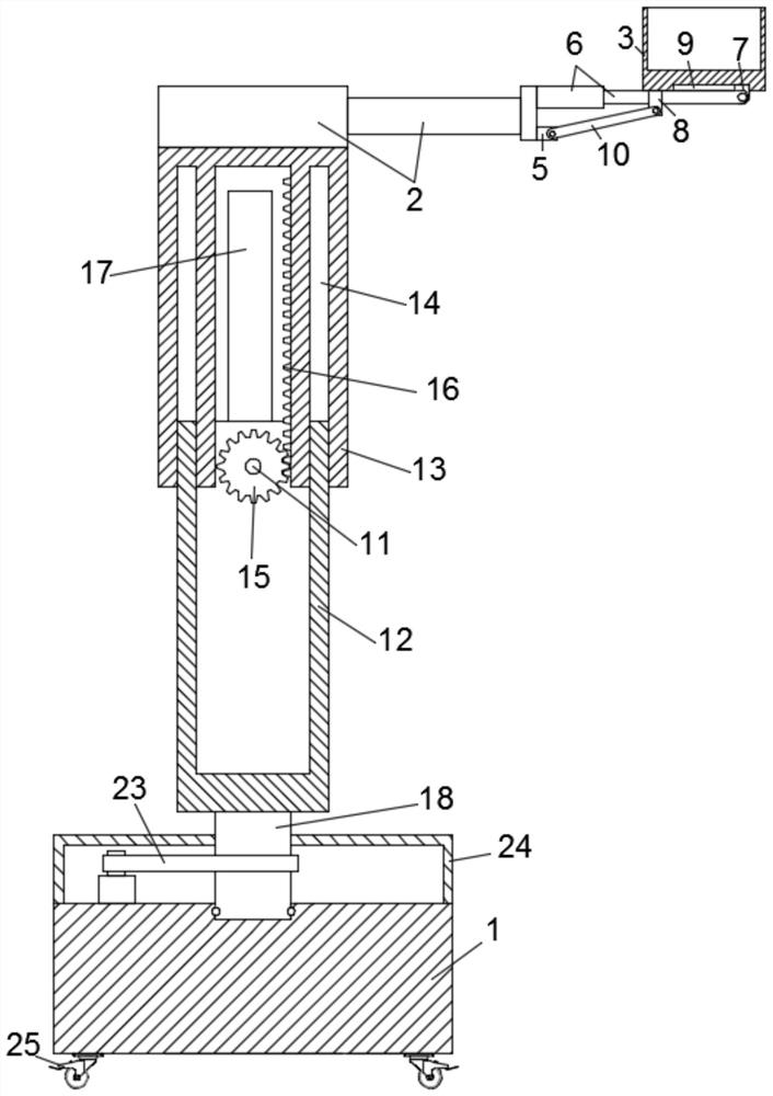
[0022] like Figure 1-3 , a multi-angle adjustable material handling device, including a handling base 1, a lifting assembly and a handling assembly, the lifting assembly is rotatably mounted on the handling base 1, the handling assembly is arranged on the lifting assembly, and the handling assembly includes The lifting cylinder 2 and the transport box 3 are fixedly installed on the lifting assembly, the lifting cylinder 2 is placed horizontally, the telescopic end of the lifting cylinder 2 is fixedly installed with a connecting plate 4, and the first fixing plate 4 is fixedly installed on the connecting plate 4 respectively. Block 5 and pneumatic push rod 6, the telescopic end of the pneumatic push rod 6 is rotated to install the slider 7, the bottom of the transport box 3 is fixedly installed with a second fixing block 8, and the bottom of the transport box 3 is provided with a sliding block 8. Slot 9, the slider 7 is slidably installed in the chute 9, a connecting rod 10 is...

Embodiment 2

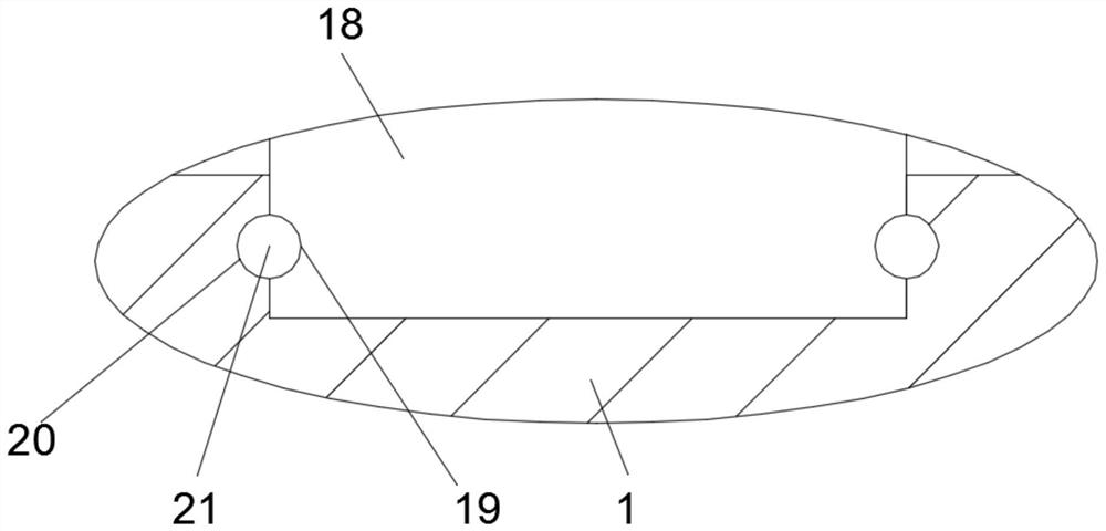
[0030] like Figure 4-5, This embodiment is further improved on the basis of Embodiment 1, and the improvement is: the inside of the carrying base 1 is provided with a blind hole 26, the bottom of the carrying base 1 is provided with a symmetrically arranged guide groove 27, and the carrying base 1 is provided with a symmetrically arranged guide groove 27. 1 is provided with a positioning assembly, the positioning assembly includes a biaxial drive motor 28 and a motor bracket 29 for fixedly installing the biaxial drive motor 28, the motor bracket 29 is fixedly installed in the blind hole 26, and the biaxial drive Positioning units are symmetrically arranged on the output shafts on both sides of the motor 28. The positioning units include a fixing plate 30 fixedly installed at the output end of the biaxial drive motor 28. An eccentric shaft pin 31 is fixedly installed on the fixing plate 30. The eccentric shaft The transition link 32 is rotated and installed on the pin 31, the ...


PUM


Abstract

The invention discloses a multi-angle adjustable material handling device, comprising a handling base, a lifting component and a handling component. The handling component includes a lifting cylinder and a handling box. The telescopic end of the lifting cylinder is fixedly installed with a connecting plate, so A first fixing block and a pneumatic push rod are respectively fixedly installed on the connecting plate, the telescopic end of the pneumatic push rod is rotated to install a slider, a second fixing block is fixedly installed at the bottom of the transport box, and the bottom of the transport box is A chute is provided, and a connecting rod is connected between the first fixed block and the second fixed block; in the present invention, by setting a lifting cylinder and a pneumatic push rod, when the pneumatic push rod is at the maximum limit position, the transport box is placed stably and the transport is driven. The box body rotates and moves to the unloading position. At this time, the pneumatic push rod shrinks, and the transport box body is gradually inclined at an angle, and the material is automatically unloaded from the transport box body, thereby avoiding manual unloading, reducing the labor intensity of the staff, saving time and effort, and improving work. efficiency.

Description

technical field [0001] The invention relates to the field of material handling, in particular to a material handling device that can be adjusted from multiple angles. Background technique [0002] The material handling device is a mechanical device that saves manpower and reduces the working intensity of the handling personnel. However, the angle of the handling components of the existing material handling device is usually not adjustable at multiple angles, so that manual unloading is still required during unloading. SUMMARY OF THE INVENTION [0003] The purpose of the present invention is to provide a multi-angle adjustable material handling device to solve the above-mentioned problems in the background art. [0004] To achieve the above object, the present invention provides the following technical solutions: [0005] A multi-angle adjustable material handling device includes a handling base, a lifting assembly and a handling assembly, the lifting assembly is rotatably...

Claims


Application Information

Patent Timeline
Patent Type & Authority Patents(China)
IPC IPC(8): B65G41/00
CPCB65G41/003
Inventor 刘绍亚吴继春王红辉熊任上王晟垚
Owner 湖南沃峰智能科技有限公司
Learn More