
Measurement system and method of manufacturing shaft with hole

一种测量系统、测量控制的技术,应用在测量装置、制造工具、测量/指示设备等方向,能够解决无法测定空心轴壁厚、误差、多余等问题

Inactive Publication Date: 2020-04-03
PROTERIAL LTD
View PDF9 Cites 6 Cited by
  • Summary
  • Abstract
  • Description
  • Claims
  • Application Information

AI Technical Summary

Problems solved by technology

[0008] In the technique of Patent Document 1, only the inner diameter of the hollow shaft can be measured, but the wall thickness of the hollow shaft cannot be measured
[0009] In addition, as a conventional method, there is a problem that in the technique of directly measuring the wall thickness with the propagation time of the ultrasonic wave incident from the outer periphery and reflected by the inner periphery, the propagation speed of the ultrasonic wave varies depending on the standard of the material. and changes, so there is an error of the order of 0.1mm
In addition, there are problems that the surface needs to be smoothed in order to introduce ultrasonic waves into the material, and redundant steps are required to measure the wall thickness.

Method used


Image

  • Measurement system and method of manufacturing shaft with hole
  • Measurement system and method of manufacturing shaft with hole
  • Measurement system and method of manufacturing shaft with hole

Examples


Embodiment 1

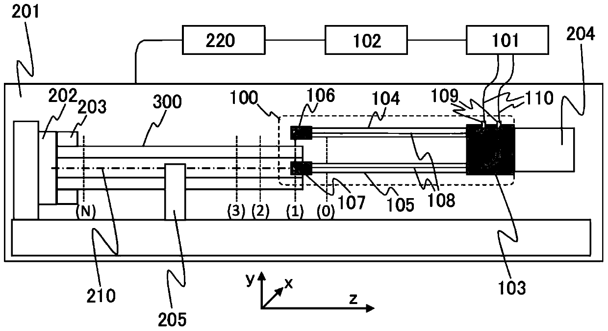
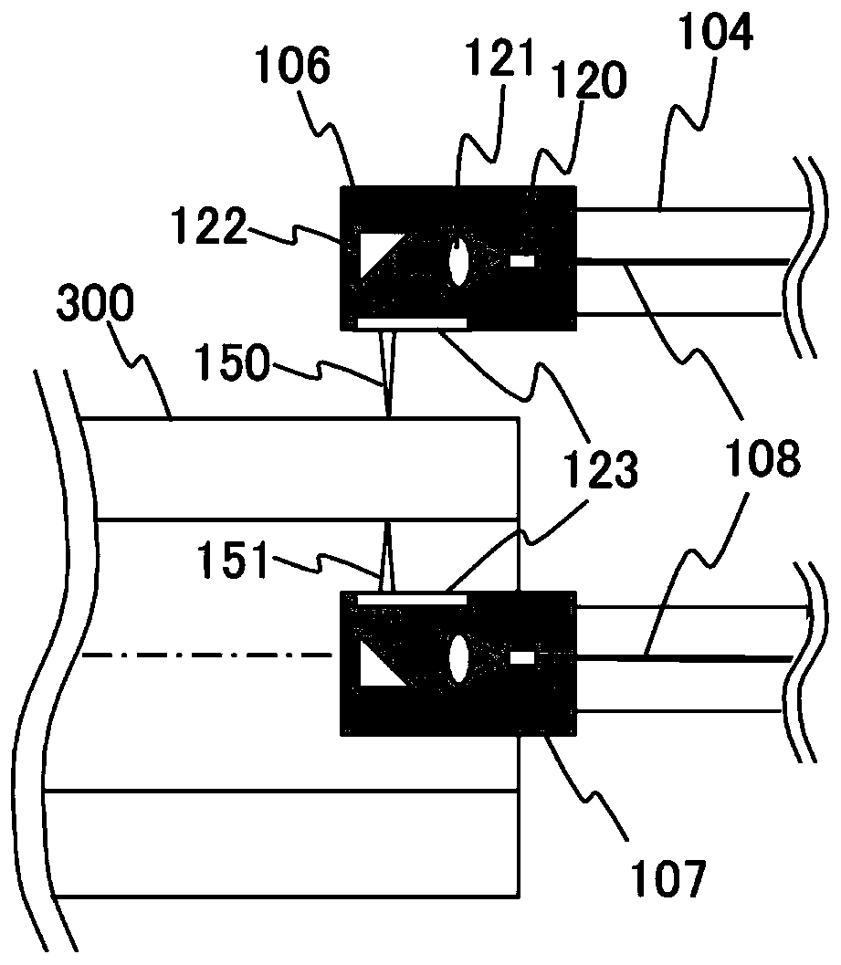
[0031] figure 1 The overall structure of the measurement system provided in the processing apparatus 201 in this invention is shown. The measurement system is a system composed of a measuring device 100 , a distance measuring device 101 , and a measurement control device 102 . In addition, the measuring device 100 is composed of measuring heads 106 and 107 , rods 104 and 105 , and a base 103 as will be described later. The distance measuring device 101 generates measurement light, and sends the measurement light to the connector 109 of the measurement device base 103 via two optical fibers 110 . The measurement device base 103 transmits measurement light to the measurement head 106 and the measurement head 107 via an optical fiber 108 . The measuring head 106 is a measuring head for the outer circumference, and the measuring head 107 is a measuring head for the inner circumference. figure 1 The outer peripheral part and the inner peripheral part of the cross-section of the ...

Embodiment 2

[0072] Next, use Figure 9 , Figure 10 , to illustrate an example of more accurately measuring the values ​​of the inner diameter and the outer diameter. Measurement is performed by moving the measuring device 100 in the -Z direction using the tool shaft / tailstock 204 of the processing device 201 , but a slight pitch or yaw (α) occurs as the tool shaft / tailstock 204 moves in the -Z direction. Even if α is an inclination that does not usually cause a problem, since the rods 104, 105 holding the measuring heads 106, 107 are long, as in Figure 9 As shown exaggeratedly in the figure, the Y-direction positions of the measuring heads 106 and 107 change somewhat. When L is the length of the rods 104 and 105, the amount of change corresponds to Lα. When L is 1000 mm or more, even if α is 100 microrads, for example, Lα becomes a displacement of 0.1 mm. This means that in Figure 4 Defined in , the value of the offset Δ between the rotation axis 210 and the surface of the protect...

Embodiment 3

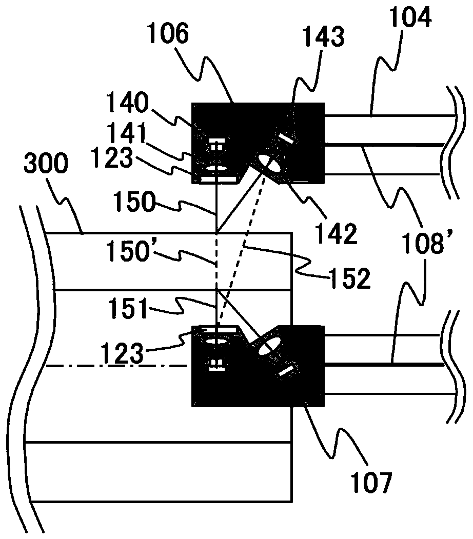
[0078] In Example 2, the deviation of the measured values ​​of the inner diameter and the outer diameter was corrected using the measurement results of other measuring instruments such as a touch probe and a micrometer, but Figure 11 An example is shown in which the deviation of the measured values ​​of the inner diameter and the outer diameter is corrected using the measuring device 100 itself.

[0079] Two or more groups of optical fiber 108, fiber end 120, lens 121, reflector 122, and protective window 123 of inner circumference measuring head 107 can be set, and additional measurement light 151' can be emitted radially. Figure 11 In (C)-1 is the structure of the case of 2 groups, Figure 11 In (C)-2 is the structure of the situation of 4 groups, Figure 11 (C)-3 in (C)-3 is the structure of the case of 3 groups.

[0080] Figure 11(A) in is the overall structure diagram of the situation of 2 groups, in this case, 1 is used for the outer circumference, and 2 is used fo...


PUM


Abstract

The invention provides a measurement system and a method of manufacturing a shaft with a hole. The measurement system of the invention includes a measuring instrument, a measurement control device, and a ranging device that is connected to the measurement control device. The measuring instrument includes a base that is to be fixed to a tool shaft, a cutter holder, or a tailstock of the machining apparatus, a first rod and a second rod that are connected to the base, and a first measuring head and a second measuring head that are fixed to the respective rods and irradiate an object to be measured with measurement light. The measurement control device (1) acquires a distance I between the first measuring head and an inner peripheral surface of the hole of the object to be measured from the ranging device, (2) acquires a distance O between the second measuring head and an outer peripheral surface of the object to be measured from the ranging device, and (3) calculates the thickness of theobject to be measured on the basis of the distance I, the distance O, and a distance between the first and second measuring heads.

Description

technical field [0001] The present invention relates to a measuring method, a measuring system, and a method for manufacturing an object having a shaft with a hole, such as a hollow (also called a through-hole) shaft, a shaft with a blind hole, and the like Background technique [0002] In the past, when there was an application to align the inner and outer axes of a hollow shaft or a shaft with a blind hole with high precision, even if the shaft end could be measured with a micrometer, etc., the measuring equipment could not enter. At the center of the shaft, it still takes man-hours to measure the thickness of the shaft using ultrasonic waves to measure the degree of uniformity of the shaft center. [0003] As a device capable of measuring the inner diameter of a hollow shaft, there is a method disclosed in Patent Document 1 in which a measuring head held at the tip of a rod is inserted into a workpiece, and the inner cross-sectional shape of the object is optically measur...

Claims


Application Information

Patent Timeline
Patent Type & Authority Applications(China)
IPC IPC(8): G01B11/06
CPCG01B11/06B23Q17/2471G01B11/08G01B11/12G01B11/24G01B2210/44G01B11/272
Inventor 渡边正浩内海幸治藤原茂吉大室佑介茅山真士
Owner PROTERIAL LTD
Learn More