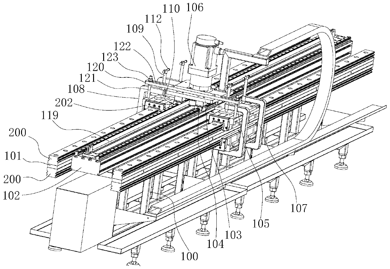
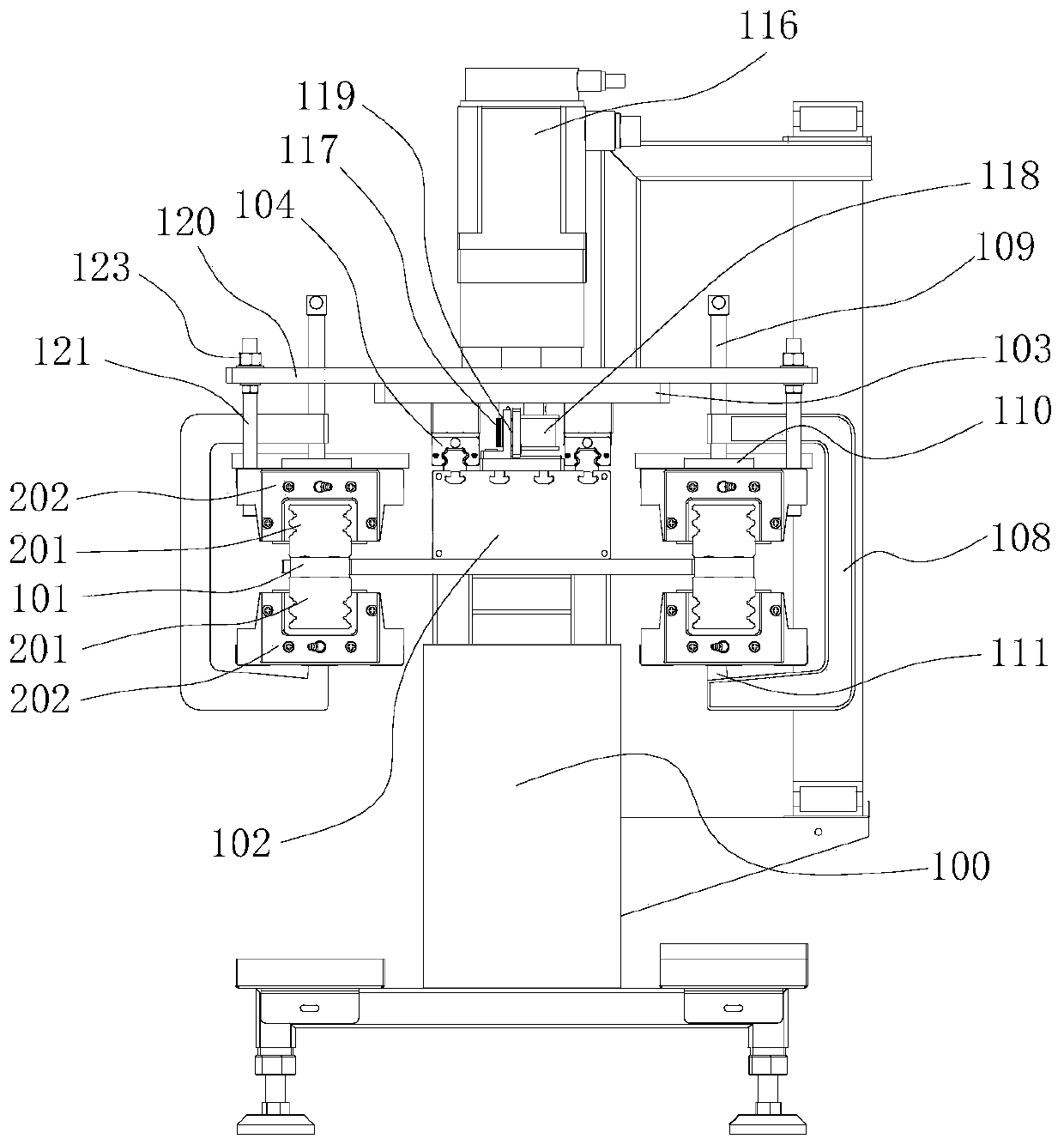
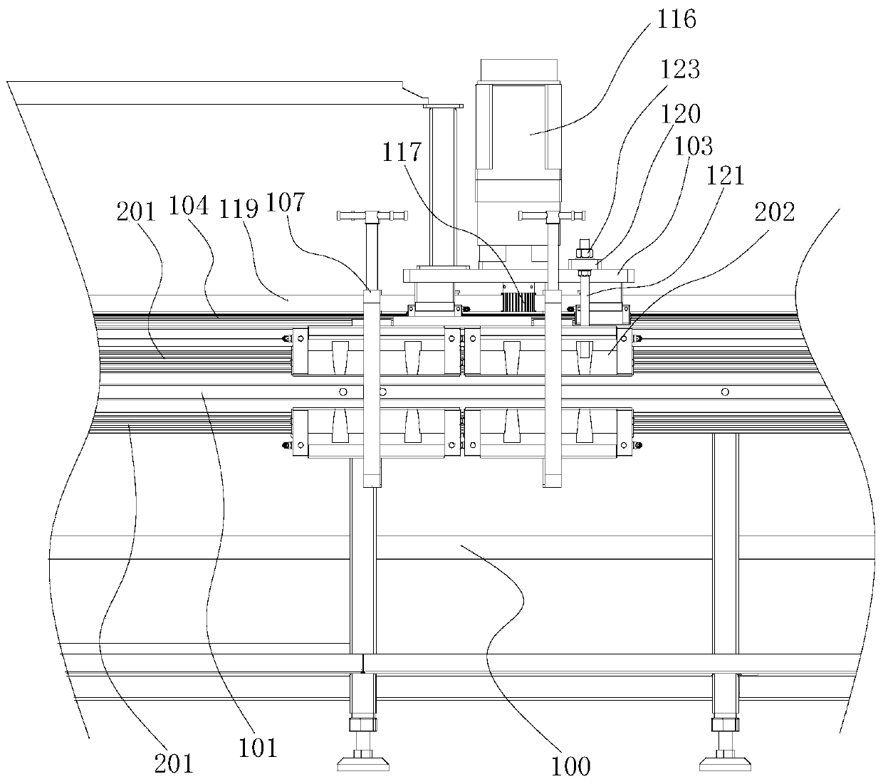
Linear guide rail pair running-in testing machine

A technology of linear guide rail pair and testing machine, which is applied in the direction of testing wear resistance, measuring devices, instruments, etc., can solve problems such as unfavorable realization, resource consumption, and lack of satisfaction, and achieve the effect of reducing running-in test costs and improving efficiency.

Pending Publication Date: 2020-04-03
JIANGMEN INTIN NUMERICAL CONTROL MACHINE TOOL CO LTD
View PDF0 Cites 2 Cited by
  • Summary
  • Abstract
  • Description
  • Claims
  • Application Information

AI Technical Summary

Problems solved by technology

In this way, the auxiliary guide rail pair 14 will bear half of the loading force, and the auxiliary guide rail pair 14 will often be replaced after one or two tests, which is troublesome and consumes resources; If the two pairs run together at the same time, the span of the gantry will be increased, the base will be wider, and the overall structure will appear huge, which is not conducive to realization; at the same time, there is no high-speed test equipment that meets the speed of 5 m / s in China.

Method used


Image

  • Linear guide rail pair running-in testing machine
  • Linear guide rail pair running-in testing machine
  • Linear guide rail pair running-in testing machine

Examples


Embodiment Construction

[0023] The specific implementation manners of the present invention will be further described in detail below in conjunction with the accompanying drawings and embodiments. The following examples are used to illustrate the present invention, but are not intended to limit the scope of the present invention.

[0024] In describing the present invention, it should be understood that the terms "center", "longitudinal", "transverse", "upper", "lower", "front", "rear", "left", " The orientation or positional relationship indicated by "right", "vertical", "horizontal", "top", "bottom", "inner", "outer", etc. is based on the orientation or positional relationship shown in the drawings, and is only for the convenience of description The present invention and simplified description do not indicate or imply that the device or element referred to must have a specific orientation, be constructed and operate in a specific orientation, and thus should not be construed as limiting the present...


PUM


Abstract

The invention discloses a running-in testing machine for a linear guide rail pair, which comprises a machine frame, guide rail mounting plates are respectively arranged on the left and right sides ofthe top of the rack; a base and a movable support are arranged in the middle of the top of the rack. An auxiliary guide rail pair connected with the base is arranged at the bottom of the movable support; connecting assemblies for fixedly connecting the sliding blocks are arranged on the left side and the right side of the movable support respectively; a driving assembly capable of driving the movable support to move back and forth on the auxiliary guide rail pair is arranged between the movable support and the base, the linear guide rail pair running-in testing machine further comprises a loading assembly capable of applying pressure to the sliding blocks, and the loading assembly is in a jaw shape and enables the two sliding blocks installed on the upper side and the lower side of the guide rail installation plate to abut against the guide rail in a pressing mode. According to the invention, the actual frictional wear condition of the linear guide rail pair under different loads and the service life of the linear guide rail pair under various speed conditions in a speed range of 5m/s can be reliably tested with low cost, and simultaneous running-in of multiple sets of guide rail pairs to be tested can be realized.

Description

technical field [0001] The invention relates to a running-in test machine for a linear guide rail pair, in particular to a test device for testing friction and wear and high-speed durability of a high-speed rolling linear guide rail pair. Background technique [0002] Rolling linear guide rail pair is a precision linear guide part, and its movement is achieved by rolling friction between the slider and the guide rail. Due to the small friction resistance of the guide rail pair, the difference between dynamic and static friction is small, and it is not easy to crawl at low speeds, and large It has been widely used in CNC machine tools, precision instruments and other fields due to its excellent characteristics such as bearing capacity, high precision, reliability and standardization. [0003] At present, the general rolling linear guide pair loading test equipment, refer to Figure 5 , the guide rail pair 11 to be tested is installed on the machine tool base 12, the slide blo...

Claims


Application Information

Patent Timeline
Patent Type & Authority Applications(China)
IPC IPC(8): G01N3/56
CPCG01N3/56G01N2203/0019G01N2203/005
Inventor 唐兵仿陈伟就汤洪波霍江峰
Owner JIANGMEN INTIN NUMERICAL CONTROL MACHINE TOOL CO LTD
Why Eureka
Try Eureka