Voltage monitoring method and device

A voltage monitoring and voltage technology, applied in the electronic field, can solve problems such as operation errors and equipment systems that cannot operate normally

Active Publication Date: 2020-04-03
GREE ELECTRIC APPLIANCES INC
View PDF6 Cites 6 Cited by
  • Summary
  • Abstract
  • Description
  • Claims
  • Application Information

AI Technical Summary

Problems solved by technology

[0006] In order to solve the above technical problems, the present invention provides a voltage monitoring method and device, which can solve the problem that in the prior art, some control modules of the equipment will run incorrectly during the fast switching process, resulting in the failure of the entire equipment system to operate normally. question

Method used


Image

  • Voltage monitoring method and device
  • Voltage monitoring method and device
  • Voltage monitoring method and device

Examples


Embodiment Construction

[0026] In order to make the purposes, technical solutions and advantages of the embodiments of the present application clearer, the technical solutions in the embodiments of the present application will be clearly and completely described below in conjunction with the drawings in the embodiments of the present application. Obviously, the described embodiments It is a part of the embodiments of this application, but not all of them. Based on the embodiments in the present application, all other embodiments obtained by persons of ordinary skill in the art without making creative efforts belong to the protection scope of the present application.

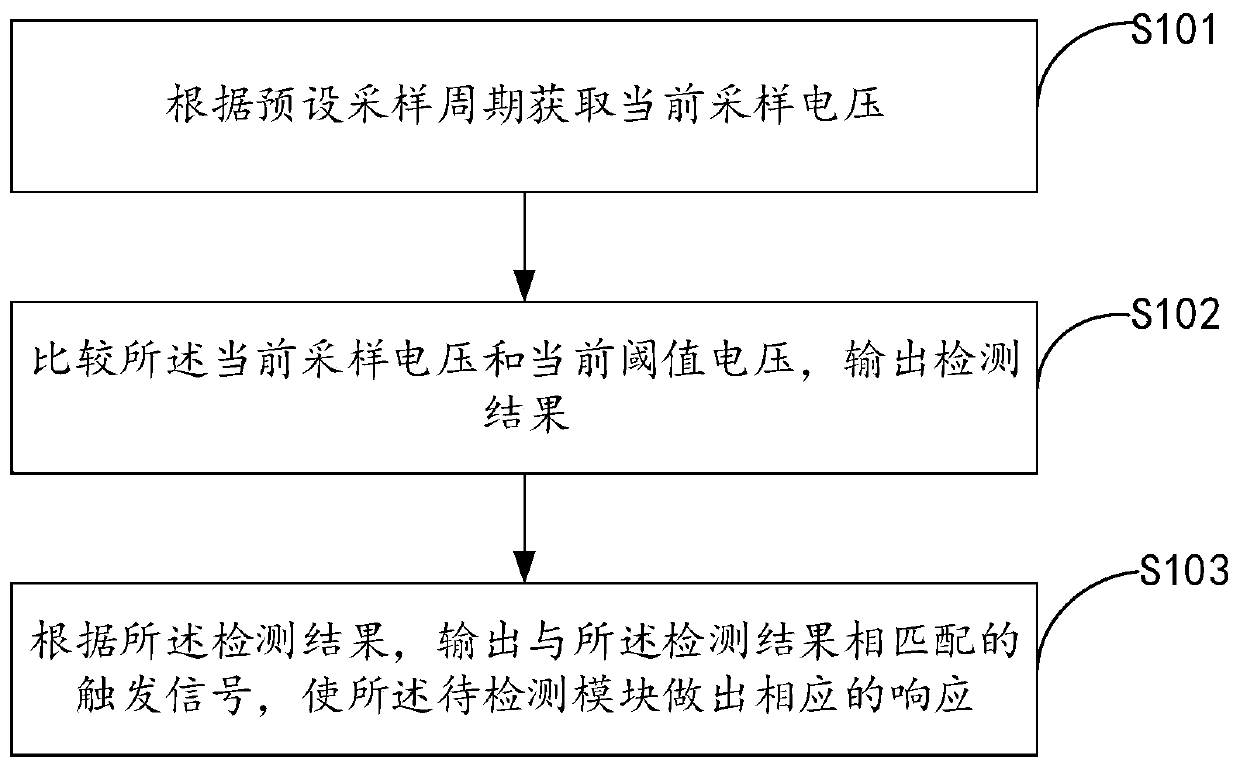
[0027] figure 1 is a flow chart of a voltage monitoring method provided by an embodiment of the present invention; figure 1 As shown, the voltage monitoring method of the present invention is applied in a voltage monitoring device and specifically includes the following steps:

[0028] In step S101, the current sampling voltage is acq...


PUM


Abstract

The invention provides a voltage monitoring method and device, and the method comprises the steps of obtaining a current sampling voltage according to a preset sampling period, wherein the current sampling voltage is the input voltage of a to-be-detected module; comparing the current sampling voltage with a current threshold voltage, and outputting a detection result; and outputting a trigger signal matched with the detection result according to the detection result, so that the to-be-detected module makes a corresponding response. According to the voltage monitoring method provided by the invention, the input voltage can be compared with the threshold voltage, and the trigger signal corresponding to the comparison result is sent out, so that the to-be-detected module can respond in time under different startup and shutdown interval durations, and the problem of operation errors can be avoided in time.

Description

technical field [0001] The present application relates to the field of electronic technology, in particular to a voltage monitoring method and device. Background technique [0002] With the rapid development of electronic technology, the concept of quality-oriented electronic equipment has become more and more popular. Good-quality equipment means that it can operate normally under various harsh and rare conditions. It is very difficult to ensure that the running response of the system works properly. [0003] At present, in order to ensure the normal operation of the equipment under the condition of fast switching on and off, a voltage detection module is installed on the total power supply module of the equipment, which is used to send a power-on reset signal to each control module after detecting that the total power supply reaches the power-on detection threshold , so that each control module can respond in time, and it is also used to send a power-off reset signal afte...

Claims


Application Information

Patent Timeline
IPC IPC(8): G01R31/40G01R19/00
CPCG01R19/0084G01R31/40
Inventor 冯玉明荣家敬张亮王静谢育桦张永光
Owner GREE ELECTRIC APPLIANCES INC
Why Eureka
Try Eureka