Gear pump floating side plate design method

A technology of floating side plate and design method, applied in design optimization/simulation, pump, mechanical equipment, etc., can solve the problems of many tests, long R&D cycle, high R&D cost, reduce the test range, facilitate calculation, and improve design The effect of efficiency

Pending Publication Date: 2020-04-03
HENAN AEROSPACE HYDRAULIC & PNEUMATIC TECH
View PDF2 Cites 2 Cited by
  • Summary
  • Abstract
  • Description
  • Claims
  • Application Information

AI Technical Summary

Problems solved by technology

[0003] The purpose of the present invention is to provide a design method for the floating side plate of a gear pump, which is used to solve the technical problems that the parameter...

Method used


Image

  • Gear pump floating side plate design method
  • Gear pump floating side plate design method
  • Gear pump floating side plate design method

Examples


Embodiment 1

[0066] In this embodiment, the adjustment of the position of the sealing strip on the floating side plate of the gear pump is used for illustration.

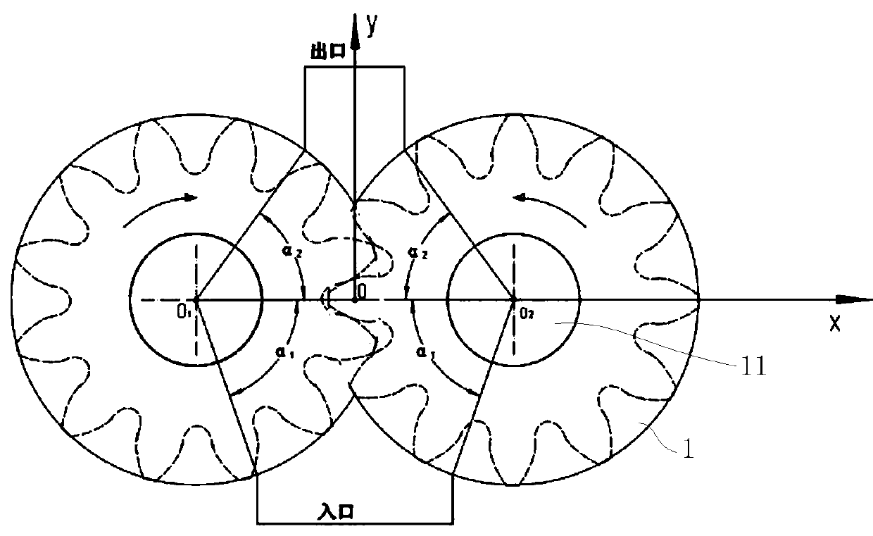
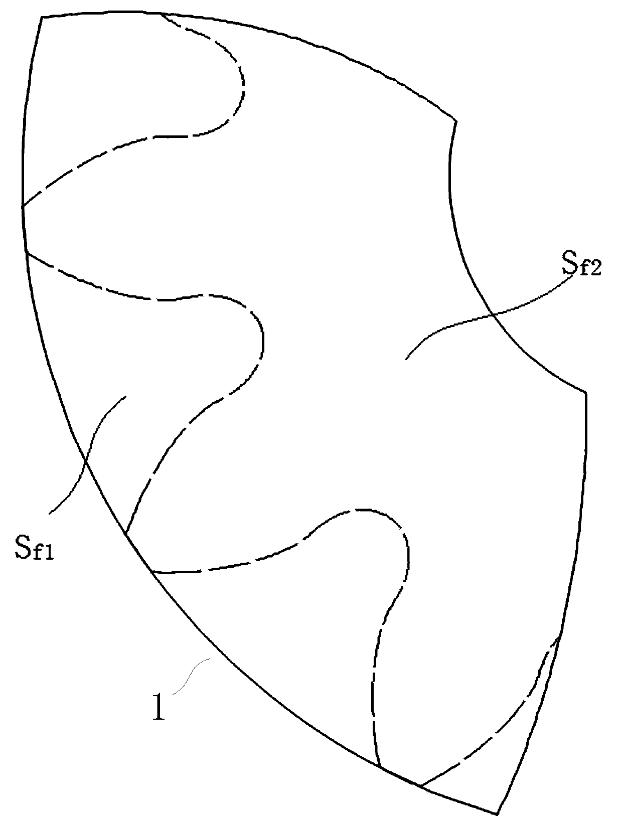
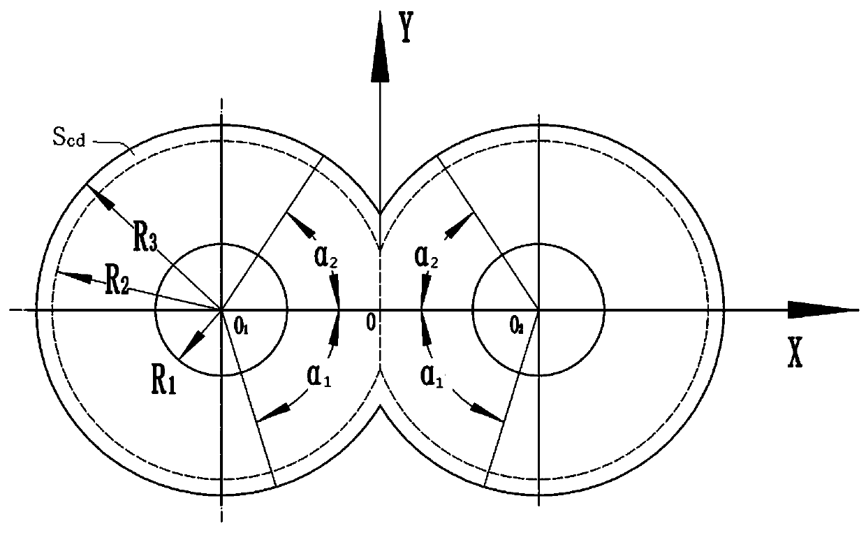
[0067] Such as Figure 1 to Figure 6 As shown, there are two rotating shaft holes 11 on the floating side plate 1, and the two rotating shaft holes 11 are used for the passing of the rotating shaft. A Cartesian coordinate system is established with the midpoint of the line connecting the centers of the two shaft holes 11 as the origin, the line connecting the centers of the two shaft holes 11 is on the X axis, and the floating side plate 1 is symmetrical about the Y axis. By calculating the force F on the side of the gear end face of the floating side plate 1 f1 , The force F on the side of the floating side plate 1 facing away from the gear yj , The floating side plate 1 is facing the gear end face and the moment M around the X axis is stressed f1-x , Moment M of floating side plate 1 around the X axis under force on the sid...

specific Embodiment 2

[0128] The only difference with the specific embodiment 1 is that in this embodiment, the wrap angle of the high pressure zone is selected as α according to experience 2 After other parameters are determined, the value of the wrap angle in the high pressure area is determined according to the parameter adjustment equation group, and then the simulation test is carried out on the floating side plate. In other embodiments, other values ​​of the parameters of the floating side plate, such as the wrap angle of the low-pressure area, can also be determined according to the parameter adjustment equations.

[0129] In other embodiments, in the gear pump floating side plate design method, F f1 , F yj , M f1-x , M yj-x Other calculation methods can be used for the calculation, such as the force F of the floating side plate towards the gear end face f1 , the part opposite to the end opening of the alveolar is not equivalent to a ring, and is calculated according to the actual area. ...


PUM


Abstract

The invention relates to the field of gear pumps, in particular to a gear pump floating side plate design method. The gear pump floating side plate design method comprises the following steps: calculating the stress of a floating side plate towards one side of a gear end surface, the stress of the floating side plate back to one side of a gear, the torque of the floating side plate towards one side of the gear end surface around an X axis and the torque of the floating side plate back to one side of the gear around the X axis, enabling the resultant force on the two sides of the floating sideplate and the resultant moment around the X axis to be zero, and listing equations: Ff1-Fyj=0, Mf1-x-Myj-x=0, and the parameter adjustment of the floating side plate needs to ensure that the resultantforce on two sides of the floating side plate and the resultant moment around the X axis are zero, so that the test range of floating side plate parameters is reduced, and the simulation test frequency of the floating side plate is reduced, and unnecessary simulation tests on the floating side plate parameters which do not meet the position adjustment equation are avoided, and the technical problems of high test frequency, long research and development period and high research and development cost caused by the fact that the existing gear pump floating side plate parameters are selected onlyby experience are solved.

Description

technical field [0001] The invention relates to the field of gear pumps, in particular to a design method for a floating side plate of a gear pump. Background technique [0002] The axial end face seal of the gear pump not only affects the volumetric efficiency of the gear pump, but also affects the life of the gear pump. The gear meshing gap leakage and radial leakage account for about 20%, and the end face leakage accounts for about 80%. In the friction pair of the gear pump, The failure rate of the end face friction pair is as high as 67.9%. At present, the high-pressure gear pump usually adopts the floating side plate to compensate the axial structure. In order to reduce the leakage of the axial end surface, a sealing strip is usually arranged on the floating side plate. The high-pressure gear oil pump includes a pump cover, a pump body, a driving gear and a driven gear. The driving gear and the driven gear are respectively installed in the pump body. The driving gear m...

Claims


Application Information

Patent Timeline
IPC IPC(8): G06F30/17G06F30/20F04C2/08F04C2/18G06F111/04G06F119/14
CPCF04C2/082F04C2/18
Inventor 赵洪锋刘伟王姗姗王向前赵亮韩正杰娄正君杨亚青张凯魏巍
Owner HENAN AEROSPACE HYDRAULIC & PNEUMATIC TECH
Why Eureka
Try Eureka