Wireless switching device, equipment, equipment system and power supply on-off operation control method

A wireless switch and equipment technology, applied in the direction of signal transmission systems, instruments, etc., can solve the problems of increasing cost, increasing the volume of the remote control terminal, and limiting the working life, so as to achieve great social and economic benefits, avoid wireless energy waste, The effect of quick on-off operation

Active Publication Date: 2020-04-03
GUANGDONG UNIV OF TECH
View PDF8 Cites 2 Cited by
  • Summary
  • Abstract
  • Description
  • Claims
  • Application Information

AI Technical Summary

Problems solved by technology

[0004] In order to solve the problem of standby power consumption, although various zero-power standby schemes have appeared, there are still many problems in these schemes, which need to be further improved and perfected.
For example, because the control signal of the existing wireless switch remote control device needs to cover a certain range to achieve operational convenience, precise directional transmission cannot be used, and the wireless energy transmission, reception and conversion process itself has relatively large losses, making wireless energy transmission efficient. Not too high, the final energy absorbed and utilized by the wireless switch device is very low, and most of the energy is radiated into the air and wasted
Another example is that the existing wireless switch remote control device needs to consume a large amount of wireless energy. Even if a high-priced, large-capacity battery is used for power supply at the remote control end, its working life will be greatly limited, and the cost will be increased.
For another example, if considering the need to ensure that the remote control signal of the wireless switch device can cover a certain range, especially hoping to achieve accurate directional transmission, then a higher requirement is proposed for the wireless switch remote control device (especially the two parts of the power amplifier and the transmitting antenna) requirements, and the existing ordinary power amplifiers and on-board patch antennas are difficult to meet the requirements, so if this kind of wireless switch device is to be used, it is necessary to increase the volume of the remote control terminal, which will bring many problems to daily applications and manufacturing costs. Negative Effects

Method used


Image

  • Wireless switching device, equipment, equipment system and power supply on-off operation control method
  • Wireless switching device, equipment, equipment system and power supply on-off operation control method
  • Wireless switching device, equipment, equipment system and power supply on-off operation control method

Examples


Embodiment approach

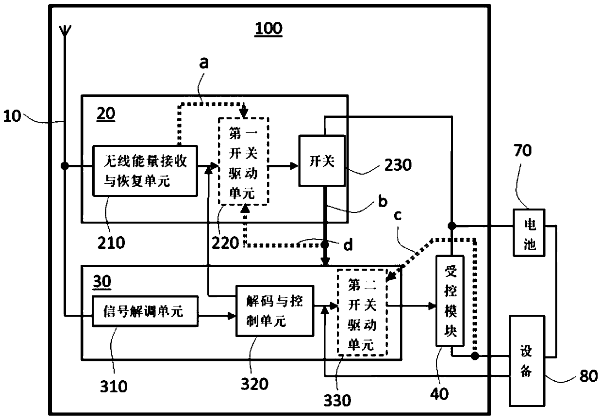
[0054] In some implementations, the wireless energy receiving and converting unit 210 can optionally be set such that the width of the pulse signal provided can ensure that the control module 30 maintains an electrical connection with the power supply before outputting the control signal, which can For example, it can be realized by providing a feedback signal to the passive wake-up module 20 by the decoding and control unit 320 in the control module 30 described below. Of course, in some other implementation manners, the wireless energy receiving and converting unit 210 may also provide the above-mentioned pulse signal all the time during the operation of the device 80 .

[0055] The switch 230 can be realized by using any suitable components, units or modules such as a monostable switch, and its control terminal can be connected with the wireless energy receiving and converting unit 210, or connected with the first switch as an optional configuration. The unit 220 is connect...


PUM


Abstract

The invention discloses a wireless switching device, equipment, an equipment system and an equipment power supply on-off operation control method. The wireless switching device is used for being arranged between a power supply and equipment which is in a passive standby state when power is not supplied, and comprises a receiving antenna which is arranged to be used for receiving a wireless signal,and the wireless signal comprises a wireless energy signal and an instruction data signal; a passive awakening module which is connected with the receiving antenna and is used for converting the wireless energy signal received by the receiving antenna into a pulse signal and outputting the pulse signal outwards; a control module which is connected with the receiving antenna and is set to be usedfor demodulating the instruction data signal received by the receiving antenna and outputting a control signal after the pulse signal output from the passive awakening module is electrically connectedwith the power supply to be supplied with power; and a controlled module which is connected with the control module, the power supply and the equipment and is used for receiving the control signal and executing on-off operation between the equipment and the power supply according to the control signal.

Description

technical field [0001] The invention relates to the technical field of switch control, and in particular to a wireless switch device, equipment, an equipment system and a method for controlling the power supply on-off operation of the equipment. Background technique [0002] With the increasing global warming, energy saving and emission reduction has become the top priority of the governments of various countries, especially the electrical and electronic industries, which are closely related to daily life and production, have been pushed to the forefront. For example, in the European and American markets, high Efficiency and low power consumption have become one of the important factors that must be considered in the research and development process of electronic products, which are more competitive in the market. [0003] The standby power consumption of various electronic devices has become one of the important problems to be solved for energy saving and emission reduction...

Claims


Application Information

Patent Timeline
Patent Type & Authority Applications(China)
IPC IPC(8): G08C17/02
CPCG08C17/02
Inventor 马建国周绍华
Owner GUANGDONG UNIV OF TECH
Why Eureka
Try Eureka