Display panel and driving method
A technology of a display panel and a driving method, which is applied to static indicators, instruments, etc., can solve the problems of burning light-emitting diodes, lowering the contrast of the picture, and a large number of micro light-emitting diodes, and achieves the effect of preventing over-current burning and improving the impact.
- Summary
- Abstract
- Description
- Claims
- Application Information
AI Technical Summary
Problems solved by technology
Method used
Image
Examples
Embodiment 1
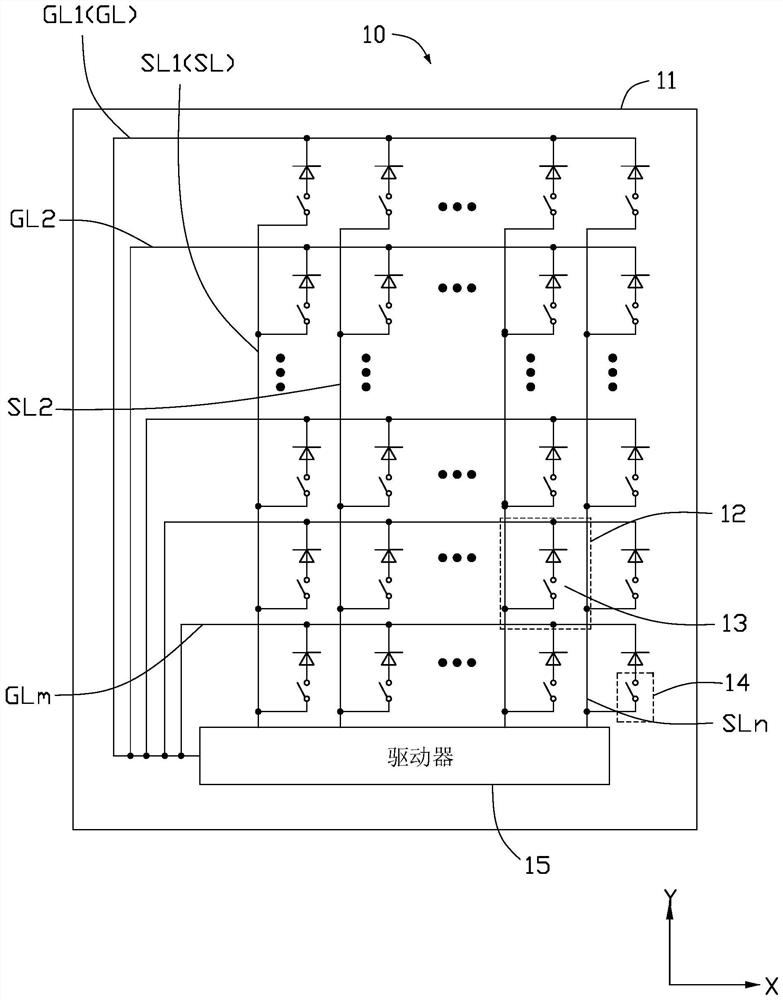
[0047] see figure 1 The display panel 10 provided in this embodiment includes a substrate 11, m gate lines (GL1˜GLm, m>2) and n data lines (SL1˜SLn, n>2) formed on the substrate 11, each The gate lines are arranged in parallel with each other at intervals, and the data lines are arranged in parallel with each other. The m gate lines and the n data lines are insulated from each other and cross each other to define a plurality of sub-pixels 12 arranged in an array, such as figure 1 As shown in , the X direction is defined as the row direction of the array, and the Y direction is defined as the column direction of the array.
[0048] read on figure 1 , the display panel 10 further includes a plurality of LEDs 13 disposed on the substrate 11 , and each LED 13 is located in a sub-pixel 12 . Each light emitting diode 13 has an anode and a cathode, the anode of each light emitting diode 13 is electrically connected to the gate line GL defining the sub-pixel 12 where it is located, ...
Embodiment 2
[0066] see Figure 5 The difference between the display panel 20 provided in this embodiment and the first embodiment mainly lies in that the circuit structure of the protection circuit 24 in this embodiment is different from that of the protection circuit 14 in the first embodiment.
[0067] In this embodiment, each protection circuit 24 includes a first switch unit 241 and a second switch unit 242 . Wherein, the first switch unit 241 is respectively electrically connected to the anode of the light emitting diode 23 and the gate line GL to which the light emitting diode 23 is electrically connected; Connect the data line SL.
[0068] read on Figure 5 , in this embodiment, the driver 25 is used to output a control signal to each protection circuit 24 to control each protection circuit 24 itself to be turned on or open, so as to control each light emitting diode 23 electrically connected to each protection circuit 24 to be kept on or short-circuited. state.
[0069] see ...
Embodiment 3
[0074] see Figure 7 The difference between the display panel 30 provided in this embodiment and the second embodiment mainly lies in that the circuit structure of the protection circuit 34 in this embodiment is different from that of the protection circuit 24 in the second embodiment.
[0075] In this embodiment, each protection circuit 34 includes a first switch unit 341 and a resistance element 342 . Wherein, the circuit structure and connection mode of the first switch unit 341 are basically the same as those of the first switch unit 241 in the second embodiment, and will not be repeated here. The resistor element 342 is respectively electrically connected to the anode of the light emitting diode 33 and the data line SL to which the light emitting diode 33 is electrically connected.
[0076] read on Figure 7 , in this embodiment, the driver 35 is used to output a control signal to each protection circuit 34 to control each protection circuit 34 itself to be turned on or...
PUM
 Abstract
Description
Claims
Application Information
 - R&D
- Intellectual Property
- Life Sciences
- Materials
- Tech Scout
- Unparalleled Data Quality
- Higher Quality Content
- 60% Fewer Hallucinations
Browse by: Latest US Patents, China's latest patents, Technical Efficacy Thesaurus, Application Domain, Technology Topic, Popular Technical Reports.
© 2025 PatSnap. All rights reserved.Legal|Privacy policy|Modern Slavery Act Transparency Statement|Sitemap|About US| Contact US: help@patsnap.com


