Electrical filter structure

A filter device and filter technology, which is applied in the direction of membrane filter, electrode conveying device, dispersed particle filtration, etc., can solve the problems of increasing fan energy and increasing fan power consumption, etc.

Pending Publication Date: 2020-04-03
LIFA AIR
View PDF20 Cites 1 Cited by
  • Summary
  • Abstract
  • Description
  • Claims
  • Application Information

AI Technical Summary

Problems solved by technology

The increased pressure drop across the filter will require a corresponding increase in the energy of the fan, which in turn increases the power consumption of the fan

Method used


Image

  • Electrical filter structure
  • Electrical filter structure
  • Electrical filter structure

Examples


Embodiment Construction

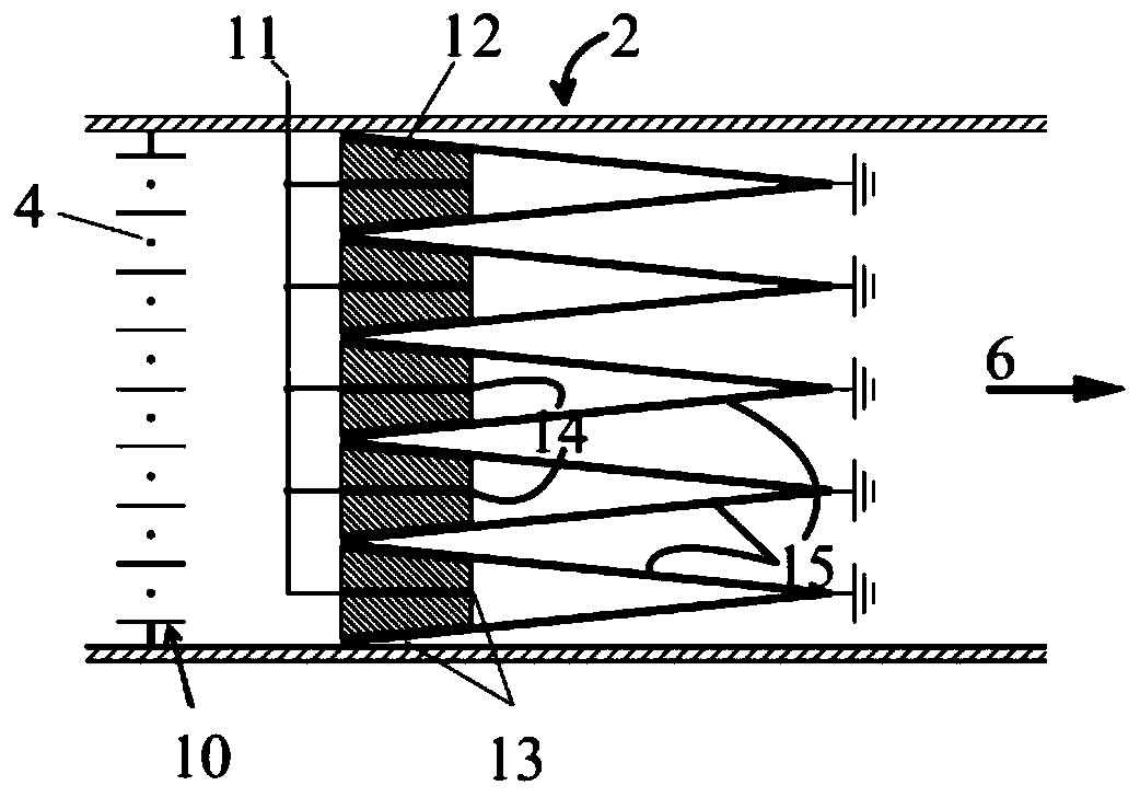
[0194] According to a preferred embodiment of the present invention, in Figure 4 A combined filter 26 and electrode unit 25 mounted together are shown in . In operation, the structure is surrounded on all sides by ventilation ducts, and the air flows from top to bottom according to the arrows in the diagram.

[0195] The electrodes 14 are arranged parallel to the air flow and covered with a suitable photocatalytic material such as TiO 2. Electrode 14 is typically aluminum, although other metals or other conductive materials may be used. On these electrode plates, UV light sources 16 are positioned on both sides of the electrodes. These light sources 16 are typically LED (Light Emitting Diode) light sources assembled on a suitable substrate, in this case a longitudinal circuit board extending deep into the filter bag 15 . Typically, the light source element is as long as the electrode 14 . On the other hand, the electrodes 14 extend almost to the end of the filter bag 15 ...


PUM


Abstract

This publication discloses a filter unit (47) connectable to a mobile communication device (45) including a fan (51) for generating an air flow (6) inside the filter unit (47), electrodes (14, 64, 68,77) covered with a photo catalytic material like Ti02in the air flow (6), UV-LEDs (16) illuminating the electrodes (64, 68,77), and outlet (6, 53, 66) for the air flow directed in direction of user offilter unit (47).

Description

technical field [0001] The invention relates to an electrostatic filter arrangement comprising a gas and particle filter according to the preamble of claim 1 . Background technique [0002] Awareness of airborne impurities and their health hazards has increased dramatically in recent years. Research has shown that gaseous and particulate impurities are environmental exposure agents that significantly increase disease and health hazards. These problems are most acute in large cities, where emissions from traffic and energy production pollute the air. In addition to being a health hazard, impurities in the outdoor air can affect the corrosion and oxidation of materials. [0003] Attempts have been made to reduce the transfer of impurities from the exterior of buildings and vehicles to indoor air by filtering incoming air. Today, mainly only particulate filters are used to clean displacement air in residential, office and commercial buildings. Only in some special occasions...

Claims


Application Information

Patent Timeline
Patent Type & Authority Applications(China)
IPC IPC(8): A61L9/22A61L9/20B03C3/017B03C3/02B03C3/155B03C3/40B03C3/47B01D46/02B01D46/00B60H3/06B01D53/02F24F3/16F24F8/167
CPCA61L9/205A61L9/22B01D46/023B01D46/50B03C3/016B03C3/08B03C3/12B03C3/155B03C3/28B03C3/368B03C3/41B03C3/47B03C3/60B03C3/86A61L2209/111A61L2209/12A61L2209/14A61L2209/16B03C2201/10B01D53/0407B01D53/8687B01D2253/102B01D2255/20707B01D2255/802B01D2258/06B01D2259/804B60H3/0078B60H3/0608B60H2003/0675Y02A50/20F24F8/192F24F8/194F24F8/167B01D46/0032B01D46/0036B01D53/007B01D2257/91B01D2279/50B03C3/017B03C3/019B03C2201/04F24F8/10F24F8/22
Inventor 珍妮特·马基帕韦萨·马基帕
Owner LIFA AIR
Why Eureka
Try Eureka