External sleeve of automatic steel ladle flow guiding device

An external sleeve and ladle technology, applied in the direction of casting molten material containers, metal processing equipment, casting equipment, etc., can solve the problems of increasing the safety hazards of oxygen burning operators, increasing inclusions, disrupting the production rhythm, etc.

Pending Publication Date: 2020-04-07
XIXIA XINYUE METALLURGICAL MATERIAL DEV CO LTD
View PDF2 Cites 2 Cited by
  • Summary
  • Abstract
  • Description
  • Claims
  • Application Information

AI Technical Summary

Problems solved by technology

Because there is a certain gap between the drainage rod and the nozzle, and there is a conical space between the drainage rod and the nozzle block, the drainage sand of the above two patent drainage devices cannot completely fill the conical space when the ladle is erected. When the ladle is erected, the high-temperature steel slag flow at the bottom side of the ladle flows into the unfilled conical space, which will cause the sintered layer of the drainage sand to thicken and deepen. When pouring begins, the molten steel will The pressure cannot break th

Method used


Image

  • External sleeve of automatic steel ladle flow guiding device
  • External sleeve of automatic steel ladle flow guiding device
  • External sleeve of automatic steel ladle flow guiding device

Examples


Embodiment Construction

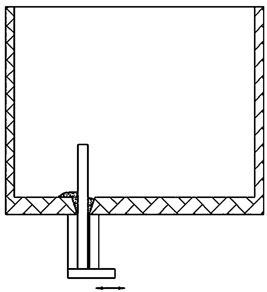
[0018] figure 1 It is an effect diagram of drainage sand filling effect diagram of a ladle automatic drainage device used in a steelmaking system disclosed on the prior art authorization announcement number CN 101543882 B authorization announcement date 2011.02.23. There is less quicksand, and steel slag will flow into the conical space, resulting in a decrease in casting rate.

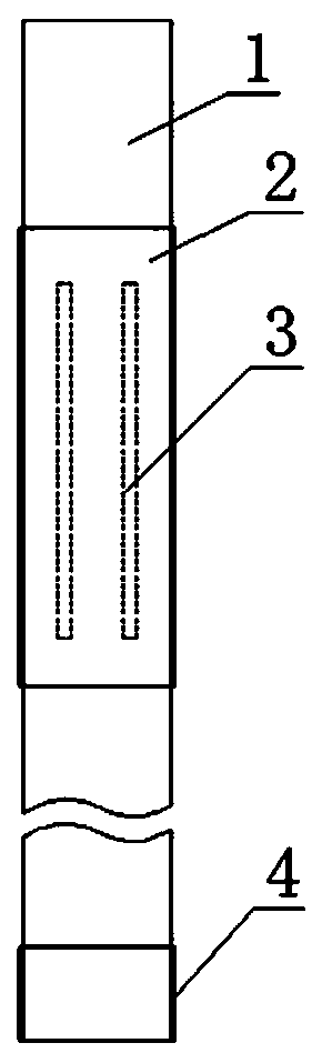
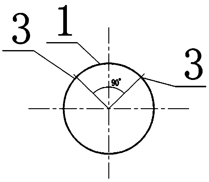
[0019] Such as figure 2 The outer casing of the ladle automatic drainage device shown in -5 of the present invention can fill the space between the drainage rod and the nozzle seat brick with drainage sand, has a high casting rate, is easy to operate, and saves labor and materials.

[0020] The outer casing of the ladle automatic drainage device has a thin-walled steel cylinder 1 containing drainage sand. The upper end of the thin-walled steel cylinder is closed, and the lower end is an open structure. The lower end of the thin-walled steel cylinder is sealed by low-temperature melting plastic 4. T...


PUM

PropertyMeasurementUnit
Lengthaaaaaaaaaa
Heightaaaaaaaaaa

Abstract

The invention discloses an external sleeve for an automatic steel ladle flow guiding device. The external sleeve is provided with a thin-wall steel cylinder for containing stuffing sand; the upper endof the thin-wall steel cylinder is closed, and the lower end of the thin-wall steel cylinder is of an open structure; the lower end of the thin-wall steel cylinder is sealed through low-temperature molten plastic; two long-strip-shaped holes are formed side by side in a side wall of the thin-wall steel cylinder in the length direction of the side wall, wherein the side wall extends out of the bottom of a steel ladle; an included angle between the two long-strip-shaped holes is 85-95 degrees; and the two long-strip-shaped holes are sealed by the low-temperature molten plastic. Compared with the prior art, the external sleeve enables the stuffing sand fills the space between a flow guiding rod and a nozzle brick cup, and has the advantages of high pouring rate, easiness in operation, labor-saving and material-saving performance.

Description

technical field [0001] The invention belongs to the technical field of ladle drainage, and in particular relates to an external casing of a ladle automatic drainage device. Background technique [0002] Ladle drainage is a key technology in iron and steel smelting. The traditional method generally uses the ladle nozzle to fill the drainage sand to realize the drainage and start pouring, which is called the sand filling method. When the drainage sand fails to automatically drain, it is necessary to use an oxygen lance to burn and blow for forced pouring. However, oxygen-rich burning and blowing will increase the oxygen content of molten steel and cause steel degradation. If the burning and blowing time is too long or the burning and blowing fails, will result in a production stoppage. Therefore, the automatic drainage rate is an important indicator to evaluate the quality of drainage agents. The drainage sand with excellent performance and high automatic drainage rate can r...

Claims


Application Information

Patent Timeline
IPC IPC(8): B22D41/44
CPCB22D41/44
Inventor 程卓
Owner XIXIA XINYUE METALLURGICAL MATERIAL DEV CO LTD
Why Eureka
Try Eureka