New energy automobile charging pile

A technology of new energy vehicles and charging piles, which is applied in the direction of electric vehicle charging technology, charging stations, electric vehicles, etc., can solve the problems of insufficient charging wire length and inability to elongate the charging wire, so as to facilitate elongation, avoid insufficient length, The effect of optimizing the setting method

Inactive Publication Date: 2020-04-07
闫长富
View PDF1 Cites 4 Cited by
  • Summary
  • Abstract
  • Description
  • Claims
  • Application Information

AI Technical Summary

Problems solved by technology

However, this patent cannot elongate the charging wire in the charging pile, and cannot avoid the occurrence of insufficient length of the charging wire in the charging pile.

Method used


Image

  • New energy automobile charging pile
  • New energy automobile charging pile
  • New energy automobile charging pile

Examples


specific Embodiment approach 1

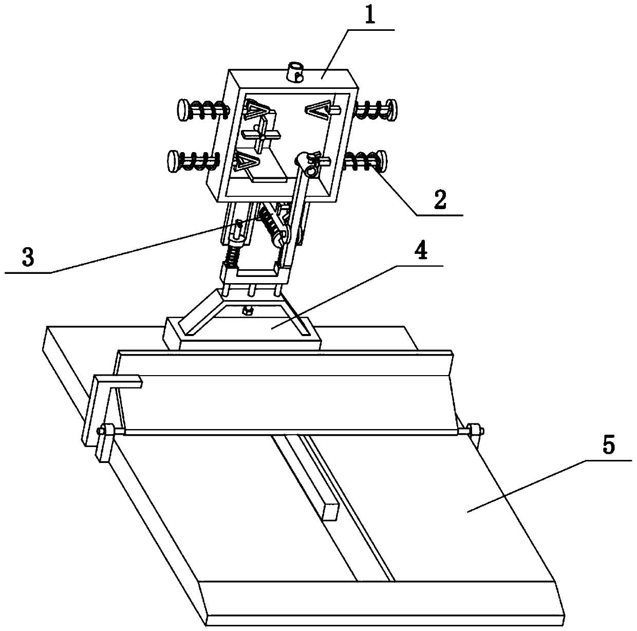
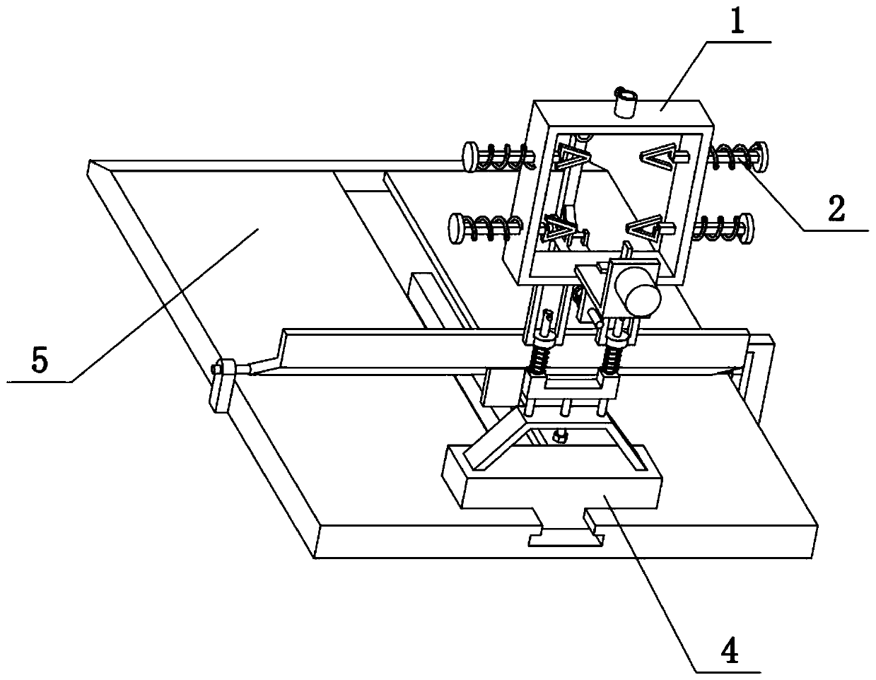
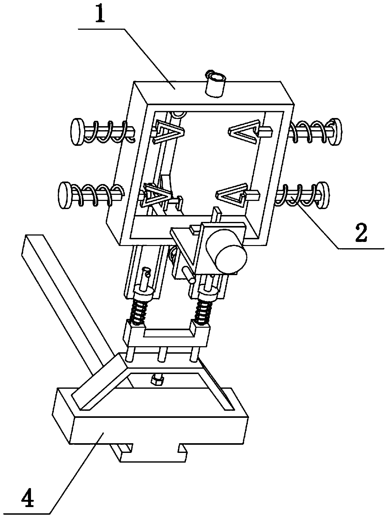
[0031] Combine below Figure 1-10 To illustrate this embodiment, the present invention relates to a charging pile, more specifically a charging pile for new energy vehicles, including a rectangular frame box 1, fastening screws I101, bushings I102, horizontal sliding posts 2, triangular rings 201, and baffles 202 and socket 203, the present invention optimizes the arrangement of the charging wire in the charging pile, which facilitates the elongation of the charging wire in the charging pile and avoids the occurrence of insufficient length of the charging wire in the charging pile.

[0032]The upper side of the rectangular frame box 1 is provided with a casing I102, the casing I102 is threadedly connected with a fastening screw I101, and the left and right sides of the rectangular frame box 1 are slidably connected with a plurality of horizontal sliding columns 2. The inner ends of the sliding posts 2 are all fixedly connected with triangular rings 201, and the plurality of tr...

specific Embodiment approach 2

[0034] Combine below Figure 1-10 To illustrate this embodiment, the new energy vehicle charging pile also includes a motor frame 105, a motor 106, and fan blades 107. The motor frame 105 is fixedly connected to the lower rear side of the rectangular frame box 1, and the motor 106 is fixedly connected to the motor frame 105. A plurality of fan blades 107 are fixedly connected to the output shaft of the motor 106 . The motor 106 can drive the fan blade 107 to rotate, thereby enhancing the heat dissipation and ventilation effect on the charging wire.

specific Embodiment approach 3

[0036] Combine below Figure 1-10 To illustrate this embodiment, the new energy vehicle charging pile also includes a fixed front pillar 3, a short round rod 308 and a connecting ear 309. Two connecting ears 309 are fixedly connected to the side, and a short round rod 308 is fixedly connected between the two connecting ears 309 . The charging wires hung on the multiple triangular rings 201 finally pass through the closed ring formed by the short round rod 308 and the two connecting ears 309 .


PUM


Abstract

The invention relates to a charging pile, particularly a new energy automobile charging pile. The pile comprises a rectangular frame box, a fastening screw I, a sleeve I, transverse sliding columns,triangular rings, a blocking piece and a socket, the arrangement mode of a charging wire in the charging pile is optimized, the charging wire in the charging pile can be lengthened conveniently, andthe situation that the length of the charging wire in the charging pile is insufficient is avoided. The sleeve I is arranged on the upper side of the rectangular frame box; the sleeve I is in threadedconnection with a fastening screw I; the left side and the right side of the rectangular frame box are slidably connected with the multiple transverse sliding columns. The triangular rings are fixedly connected to the inner ends of the multiple transverse sliding columns, inserting openings are formed in the multiple triangular rings, the multiple triangular rings are located on the inner side ofthe rectangular frame box, blocking pieces are fixedly connected to the outer ends of the multiple transverse sliding columns, the multiple transverse sliding columns are sleeved with compression springs I, and the multiple compression springs I are located on the outer side of the rectangular frame box.

Description

technical field [0001] The invention relates to a charging pile, in particular to a new energy vehicle charging pile. Background technique [0002] The application number is CN201720389224.5, which discloses an integrated electric vehicle charging pile. The utility model relates to the technical field of electric vehicle charging, in particular to an integrated electric vehicle charging pile, which includes a charging pile housing, and a charging module is arranged inside the housing. The main control unit uses the STM chip as the core processor to control the metering module, communication module, printing module, storage module, GSM signal transmitting module and human-computer interaction module to complete the corresponding functions. The printing output port of the printing module is set in the housing. The computer interaction module is embedded and fixed in the groove of the housing, and one side of the housing is provided with a card slot for placing the charging gun...

Claims


Application Information

Patent Timeline
Patent Type & Authority Applications(China)
IPC IPC(8): B60L53/31B60L53/18
CPCB60L53/18B60L53/31Y02T10/70Y02T10/7072Y02T90/12Y02T90/14
Inventor 闫长富
Owner 闫长富
Why Eureka
Try Eureka