Filling pipe capable of effectively preventing materials from gushing out

A technology for filling tubes and materials, applied in packaging and other directions, can solve problems such as appearance wrinkles, poor use effect, and dents, and achieve good visual effects and full-bodied finished products

Inactive Publication Date: 2020-04-07
罗仕泽
View PDF2 Cites 0 Cited by
  • Summary
  • Abstract
  • Description
  • Claims
  • Application Information

AI Technical Summary

Problems solved by technology

However, the actual use effect is not good, not only wasting a lot of internal space of the flexible packaging container, but also unable to prevent the material from gushing out, resulting in the contamination of the filling tube body and the outer wall of the flexible packaging container, and the liquid material in the flexible packaging container cannot support the flexible packaging container. Shape, causing appearance wrinkles, depressions, flexible packaging containers can not be upright and other adverse effects, seriously affecting the perception of consumers and the normal storage and use of flexible packaging containers

Method used


Image

  • Filling pipe capable of effectively preventing materials from gushing out
  • Filling pipe capable of effectively preventing materials from gushing out
  • Filling pipe capable of effectively preventing materials from gushing out

Examples


Embodiment 1

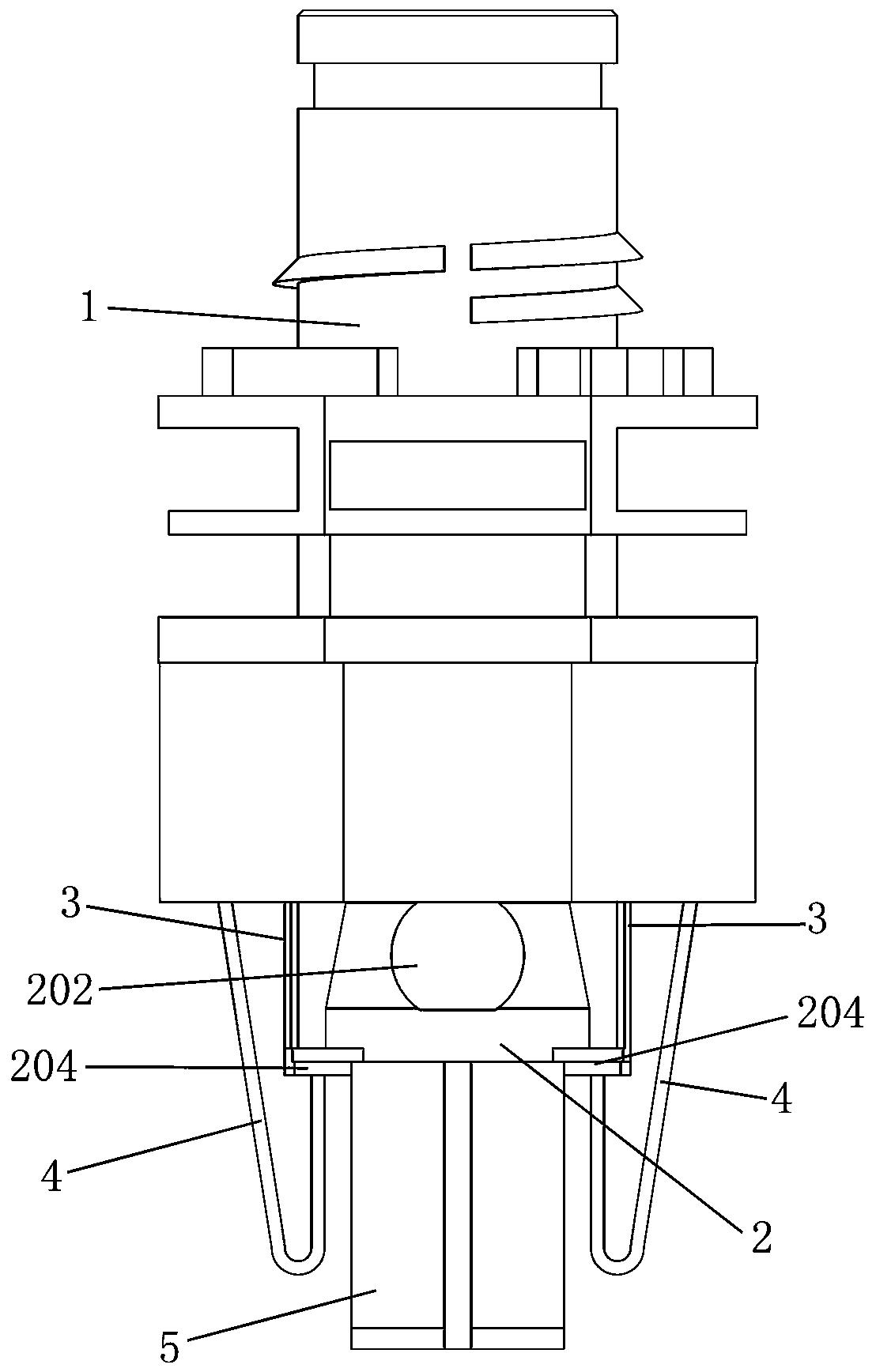
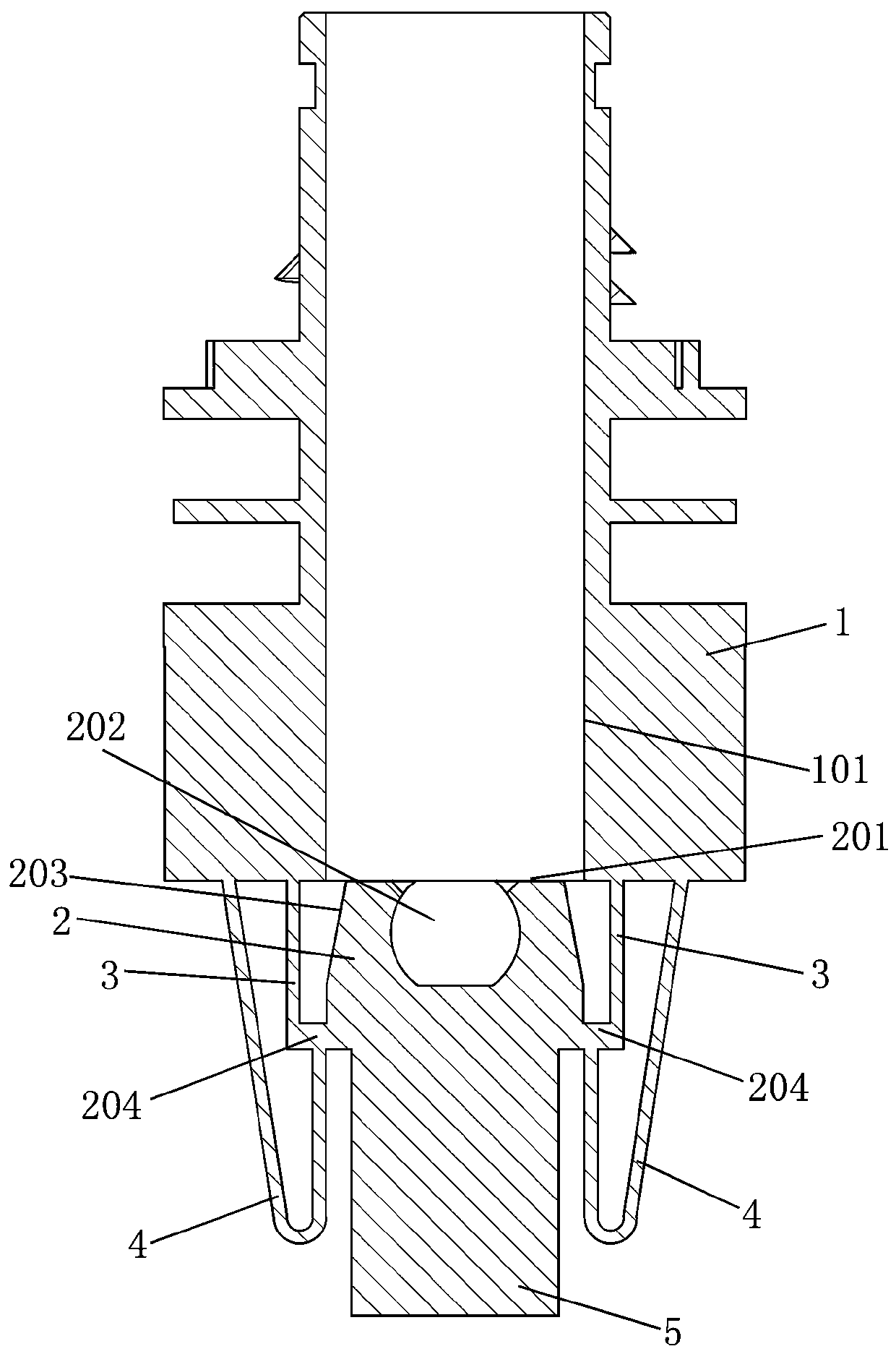
[0027] like Figure 1-8 As shown, the filling pipe in this embodiment that can effectively prevent materials from gushing out includes a filling pipe body 1 and a valve body 2. There is a filling channel 101 between the top and bottom surfaces of the filling pipe body 1, and the valve body 2 Connect the filling pipe body 1 through two breakable connecting wires 3, the two breaking connecting wires 3 are respectively located on the left and right sides of the filling pipe body 1, and the valve body 2 is located in the filling channel of the filling pipe body 1 Below the bottom opening of 101, there is a deformable ball pit 202 on the top surface 201 of the valve body; the bottom end of the outer surface 203 of the valve body 2 has two steps 204 that can be stuck at the bottom opening of the filling channel 101 of the filling pipe body 1 , the number of the steps 204 is two, and the two steps 204 are respectively located on the left and right sides of the valve body 2 . The ste...

Embodiment 2

[0039] The difference between the filling pipe that can effectively prevent the material from gushing out in this embodiment and that in Embodiment 1 is that:

[0040] The outer diameter of the outer surface 203 of the valve body 2 within 1 mm above the step 204 is equal to the inner diameter of the filling channel 101 .

[0041] The number of steps 204 is one, and the steps 204 extend along the circumference of the outer surface 203 of the valve body 2 to form a closed ring.

Embodiment 3

[0043] The difference between the filling pipe that can effectively prevent the material from gushing out in this embodiment and that in Embodiment 1 is that:

[0044] The outer diameter of the outer surface 203 of the valve body 2 located within 3 mm above the step 204 is equal to the inner diameter of the filling channel 101 .

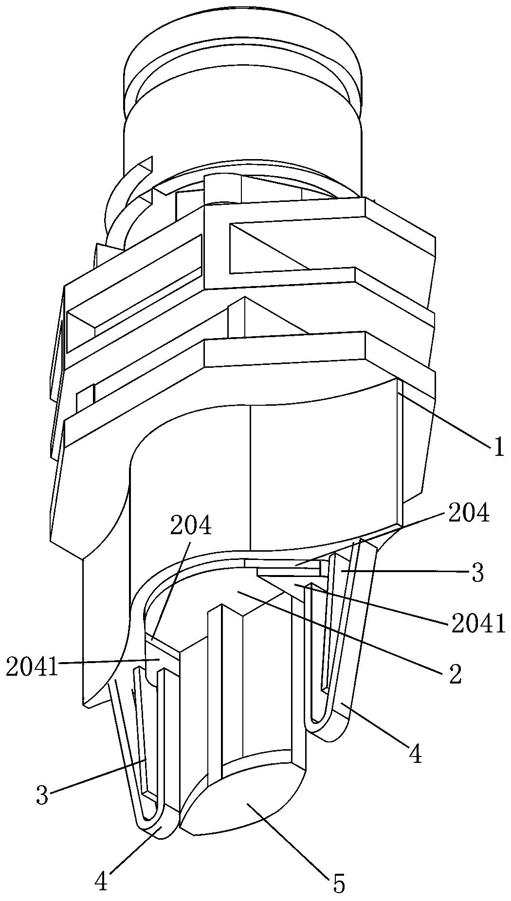
[0045] The two stepped bottom surfaces 2041 of the valve body 2 are not designed to connect the valve line 4 nor the switch handle 5 . Therefore, before the consumer uses it, it is necessary to use a rod or stick to extend from the top of the filling channel 101 to poke the valve body 2 out from the bottom opening of the filling channel 101, which is inconvenient to use.


PUM


Abstract

The invention discloses a filling pipe capable of effectively preventing materials from gushing out. The filling pipe comprises a filling pipe body, a filling channel is formed between the top face and the bottom face of the filling pipe body, the filling pipe further comprises a valve body, the valve body is connected to the filling pipe body through at least one breakable connecting wire and located below an opening in the bottom end of the filling channel of the filling pipe body, a deformable ball pit is formed in the top face of the valve body, and the bottom end of the outer side face ofthe valve body is provided with at least one step capable of clamping an opening in the bottom end of the filling channel of the filling pipe body. According to the filling pipe, the valve body, thebreakable connecting wire, the connecting valve wire, the switch handle and other structures are arranged, therefore, the filling channel can be blocked in time when the filling gun is pulled out, liquid materials are effectively prevented from gushing out along with the filling gun, the filling pipe body and the outer side wall of the flexible package container are prevented from being polluted by the liquid materials, more than 80% of materials can be filled, the volume of the flexible package container is fully utilized, a manufactured finished product is full and can well stand by itself,and a good visual effect can also be obtained.

Description

technical field [0001] The invention relates to a filling pipe, more specifically to a filling pipe capable of effectively preventing materials from gushing out. Background technique [0002] Filling tubes are widely used in flexible packaging containers. Usually, the filling tube includes a filling tube body, and a filling channel is opened between the top surface and the bottom surface of the filling tube body. [0003] At present, the filling gun of the filling equipment is usually inserted from the top opening of the filling channel of the filling tube body to fill the liquid material. When the filling gun rises and leaves the filling channel after filling, the liquid material in the flexible packaging container is easily Following the filling gun and pouring out from the filling channel, not only will it cause a lot of waste, but it will also cause the body of the filling tube and the outer wall of the flexible packaging container to be polluted, which is extremely diff...

Claims


Application Information

Patent Timeline
Patent Type & Authority Applications(China)
IPC IPC(8): B65D75/58
CPCB65D75/5883
Inventor 罗仕泽
Owner 罗仕泽
Why Eureka
Try Eureka