
Lifting type circulating transportation device

A transport device, a lift-type technology, applied in the field of lift-type circular transport devices, can solve the problems that affect the stability and safety of the transport trolley, the inability to lift the wire tube, and low operating stability, so as to achieve a good connection effect and avoid Hooking problem, effect of improving conveying efficiency

Active Publication Date: 2020-04-07
STATE GRID CORP OF CHINA +2
View PDF7 Cites 0 Cited by
  • Summary
  • Abstract
  • Description
  • Claims
  • Application Information

AI Technical Summary

Problems solved by technology

However, due to the fact that most of the existing routing methods for transporting trolleys use drag chains or cable carriages, and this type of routing mechanism can only realize the horizontal movement of the wire tubes, and cannot make the wire tubes rise and fall with the height of the transporting trolleys, thus As a result, in order to achieve stable movement of the transport trolley on the upper floor, it is necessary to reserve a sufficient length of wire tube between the transport trolley and the routing mechanism
As a result, when the conveying trolley is at a low position, this part of the line pipe will be dragged on the ground and rub against the ground; when the conveying trolley is at a high position, this part of the line pipe will hang on the conveying trolley and shake back and forth, making it easy for the line pipe to come out of contact with the ground. The problem of hooking and breaking off of external equipment has seriously affected the running stability and safety of the conveying trolley
Therefore, the existing lifting conveying trolley has the problems of low running stability and poor safety when in use.

Method used


Image

  • Lifting type circulating transportation device
  • Lifting type circulating transportation device
  • Lifting type circulating transportation device

Examples


Embodiment Construction

[0023] The present invention will be further described below in conjunction with the accompanying drawings and embodiments, but not as a basis for limiting the present invention.

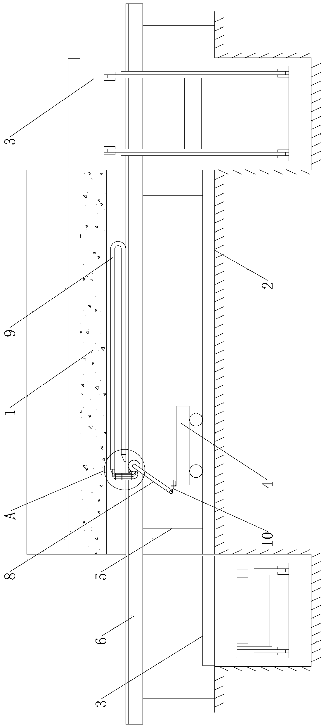
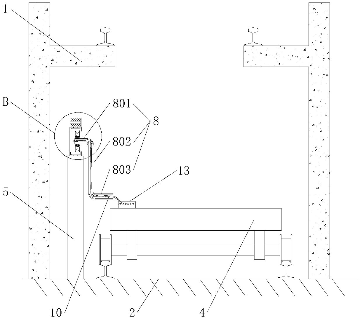
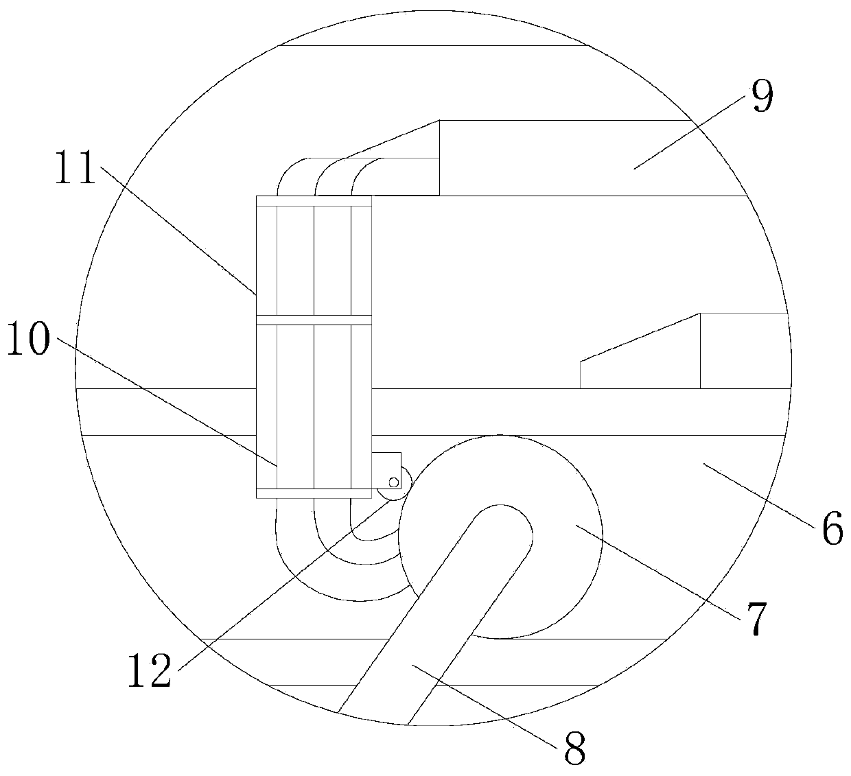
[0024] Example. Lifting circular transport device, constituted as figure 1 As shown, including the upper platform 1 and the lower platform 2, the first conveying track is laid on the upper platform 1 and the lower platform 2, and the two ends of the upper platform 1 and the lower platform 2 are provided with a scissor lift platform 3, and the scissor lift The platform 3 is provided with a second conveying track, the first conveying track and the second conveying track are provided with a conveying trolley 4, and one side of the conveying trolley 4 is provided with a routing mechanism positioned at the lower platform 2; the routing mechanism includes a routing mechanism Frame 5, the top of the cable rack 5 is provided with a guide frame 6, the guide frame 6 is provided with a rolling wheel 7 through...


PUM


Abstract

The invention discloses a lifting type circulating transportation device. The lifting type circulating transportation device comprises an upper-layer platform and a lower-layer platform, first conveying rails are laid on the upper-layer platform and the lower-layer platform, shear fork type lifting platforms are arranged at the two ends of the upper-layer platform and the two ends of the lower-layer platform, second conveying rails are arranged on the shear fork type lifting platforms, conveying trolleys are arranged on the first conveying rails and the second conveying rails, and wiring mechanisms located on the lower-layer platform are arranged on one sides of the conveying trolleys. Each wiring mechanism comprises a wiring frame, guide frames are arranged at the tops of the wiring frames, rolling wheels are arranged in the guide frames through guide rails, rotatable wiring pipes are arranged in the middles of the rolling wheels, drag chains are arranged at the tops of the guide frames, trolley buses are connected in the drag chains, and the ends of the trolley buses penetrate through the wiring pipes to be connected with the conveying trolleys after extending into the guide frames close to one sides of the wiring pipes. The lifting type circulating transportation device has the characteristics of high operation stability and good safety.

Description

technical field [0001] The invention relates to a lifting transport device, in particular to a lifting cycle transport device. Background technique [0002] In the factory buildings of hydropower stations, it is often necessary to transport large items over long distances and across floors. At present, the transport method for such items is carried by a transport trolley. The transport trolley moves horizontally under the drive of the motor, and uses the lifting Lifting equipment such as elevators lifts the conveying trolley loaded with heavy objects as a whole, so as to realize its transportation work. The hydraulic and electrical components on the conveying trolley need to be connected to the external control cabinet through power lines and signal lines to achieve control and drive. However, due to the fact that most of the existing routing methods for transporting trolleys use drag chains or cable carriages, and this type of routing mechanism can only realize the horizon...

Claims


Application Information

Patent Timeline
Patent Type & Authority Applications(China)
IPC IPC(8): B65G35/00B66F7/06B66F7/28
CPCB65G35/00B66F7/065B66F7/28
Inventor 洪达正苏静蔡海涛杨雷薛童童
Owner STATE GRID CORP OF CHINA
Learn More