Silicon wafer interlayer configuration mechanism

A technology of interlayer and silicon wafer, applied in the direction of conveyor objects, transportation and packaging, etc., can solve the problems of cumbersome boxing, high dependence on personnel, and increased boxing costs, so as to prevent insufficient supply of materials and ensure real-time monitoring Effect

Pending Publication Date: 2020-04-07
HANGZHOU ZHONGWEI PHOTOELECTRICITY
View PDF0 Cites 0 Cited by
  • Summary
  • Abstract
  • Description
  • Claims
  • Application Information

AI Technical Summary

Problems solved by technology

[0002] Since the silicon wafers are fragile, in order to avoid damage during transportation, the silicon wafers are packed in foam boxes, each box of silicon wafers is separated by foam, and a piece of corrugated cardboard is placed on the outermost layer, so that the silicon wafers The film is relatively static in the foam box, and there is foam cushioning protection during transportation to avoid collision damage. Because this "sandwich" boxing method is cumbersome, the traditional boxing method is still manual. The packing efficiency is not high, the personnel dependence is high, and the packing cost is increased

Method used


Image

  • Silicon wafer interlayer configuration mechanism
  • Silicon wafer interlayer configuration mechanism
  • Silicon wafer interlayer configuration mechanism

Examples


Embodiment 1

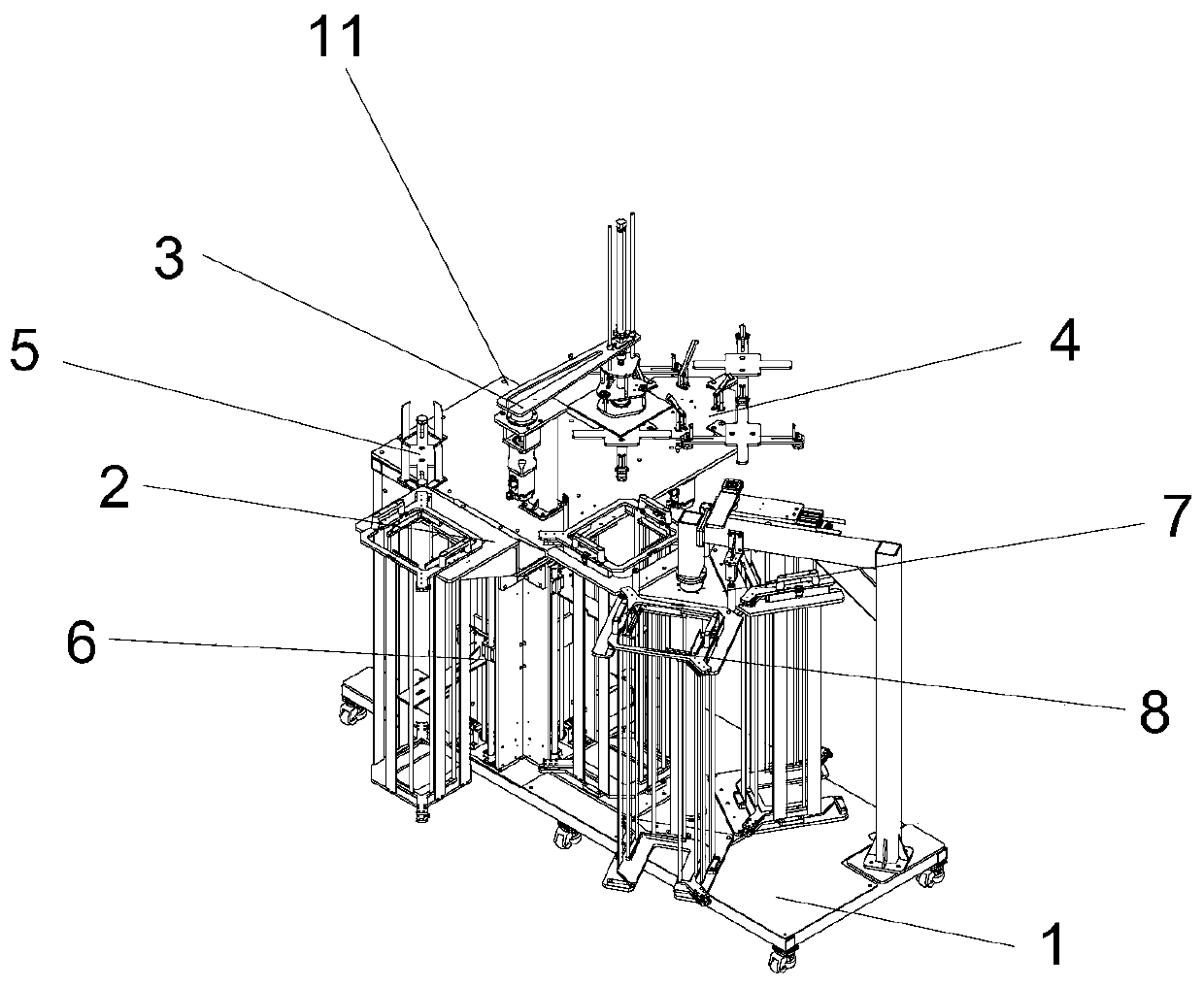
[0033] In the process of packaging silicon wafers, a certain number of silicon wafers need to be separated, so different types of interlayers are required. The materials for the interlayer include corrugated board, sulfuric acid paper, and pearl cotton. Silicon wafers can only be in contact with sulfuric acid paper. , so three different interlayers are required, including corrugated board, pearl cotton, sulfuric acid paper from top to bottom, sulfuric acid paper, pearl cotton, sulfuric acid paper, sulfuric acid paper, pearl cotton, corrugated board, manual configuration is time-consuming and laborious, so the design is as follows figure 1 The silicon wafer interlayer configuration mechanism shown includes a frame 1, an auxiliary material lifting device 2, a material preparation rotary manipulator 3, an interlayer material preparation turntable 4, a sulfuric acid paper batching table 5, a lifter 6, a pearl cotton feeding rotary platform 7, and auxiliary materials Lifting device ...

Embodiment 2

[0041] As shown in Embodiment 1, a silicon chip interlayer configuration mechanism differs only in that two guide pillars 66 are fixed inside the outer frame 61, and the guide pillars 66 are respectively fixed on both sides of the synchronous belt 64, and the lifting plate 65 Linear bearings 67 are respectively installed on both sides of the two sides, and the linear bearings 67 are slidably installed on the guide post 66 . By setting the guide post 66 and the linear bearing 67, it is ensured that the lifting plate 65 remains stable during the lifting process.

Embodiment 3

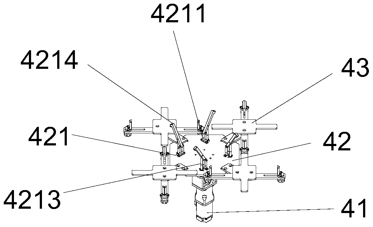
[0043] A kind of silicon wafer interlayer configuration mechanism as shown in embodiment 1, its difference is only, also be provided with a pressing mechanism 421 on one side of each adjusting frame 43, and pressing mechanism 421 is installed on the rotary table 42, presses The tightening mechanism 421 is used to compress the arranged interlayer to ensure that after the interlayer is arranged, the interlayer will not float away during the rotation of the turntable.

[0044] The pressing mechanism 421 is made up of a jacking frame 4211, a jacking cylinder 4212, a jacking guide post 4213, and a pressing plate 4214. One end of the jacking frame 4211 is fixed on the table top of the rotary table 42, and one end of the pressing plate 4214 is rotatably mounted on the top of the jacking frame 4211. At the other end, one end of the lifting guide post 4213 passes through the turntable 42 and is fixed on the pressure plate 4214 , and the other end of the lifting guide post 4213 is connec...


PUM


Abstract

The invention discloses a silicon wafer interlayer configuration mechanism. The mechanism comprises a rack, an auxiliary material lifting device, a material preparation rotary manipulator, an interlayer material preparation rotary table, a sulphuric acid paper batching table, a lifter and a pearl wool supply rotary platform, wherein the auxiliary material lifting device, the material preparation rotary mechanical arm, the interlayer material preparation rotary table, the sulphuric acid paper batching table, the lifter and the pearl wool feeding rotary platform are all installed on the rack, and integration of interlayer configuration mechanisms is achieved. The mechanism has the advantages that the material preparation rotary manipulator is matched with a program to rotate, different prepared materials are sucked to the interlayer material preparation rotary table according to different sequences, configuration of different types of interlayers is achieved, tedious manual configurationcan be effectively replaced, and the mechanism is low in personnel dependence and high in silicon wafer interlayer configuration rate.

Description

technical field [0001] The invention relates to silicon wafer box packing equipment, in particular to a silicon wafer interlayer configuration mechanism. Background technique [0002] Since the silicon wafers are fragile, in order to avoid damage during transportation, the silicon wafers are packed in foam boxes, each box of silicon wafers is separated by foam, and a piece of corrugated cardboard is placed on the outermost layer, so that the silicon wafers The film is relatively static in the foam box, and there is foam cushioning protection during transportation to avoid collision damage. Because this "sandwich" boxing method is cumbersome, the traditional boxing method is still manual. The boxing efficiency is not high, and the personnel dependence is high, which increases the boxing cost. Contents of the invention [0003] The technical problem to be solved by the present invention is to provide a silicon wafer interlayer configuration mechanism in view of the above pr...

Claims


Application Information

Patent Timeline
IPC IPC(8): B65G47/74B65G47/90
CPCB65G47/74B65G47/904
Inventor 叶欣胡普查张广犬孙培文王俊王亚伟黄游谢可馨
Owner HANGZHOU ZHONGWEI PHOTOELECTRICITY
Why Eureka
Try Eureka