Semiconductor lead electroplating equipment

A technology for electroplating equipment and semiconductors, applied in semiconductor devices, plating tanks, circuits, etc., can solve the problems affecting the efficiency and quality of electroplating, increase production costs, and cannot deal with bubbles in the electroplating liquid, so as to ensure the quality of electroplating, low manufacturing costs, Easy to use effect

Active Publication Date: 2020-04-07
泰州市昶宇电气科技有限公司
View PDF7 Cites 1 Cited by
  • Summary
  • Abstract
  • Description
  • Claims
  • Application Information

AI Technical Summary

Problems solved by technology

[0002] In the production process of semiconductors, it is necessary to use electroplating equipment to plate tin on its leads. Traditional semiconductor electroplating equipment includes barrel plating and rack plating. The barrel plating includes a roller and a copper rod horizontally arranged in the roller. As an electroplating cathode, barrel plating is suitable for the electroplating of small parts that cannot be or are not suitable for hanging due to factors such as shape and size. Compared with early small parts electroplating using rack plating or basket plating, it saves labor and improves Labor production efficiency, but the existing equipment cannot make the electroplating solution fully contact with the lead wires and cannot deal with the bubbles remaining in the electroplating solution, which affects the electroplating efficiency and quality, and increases the production cost

Method used


Image

  • Semiconductor lead electroplating equipment
  • Semiconductor lead electroplating equipment
  • Semiconductor lead electroplating equipment

Examples


Embodiment Construction

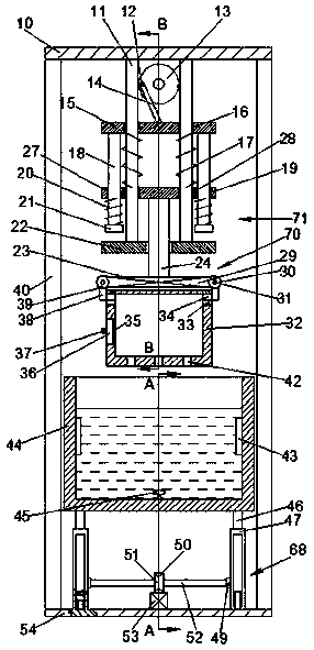
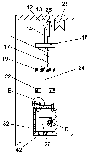
[0018] Combine below Figure 1-7 The present invention will be described in detail. For the convenience of description, the orientations mentioned below are now specified as follows: figure 1 The vertical, horizontal, front and rear directions of the projection relationship are the same.

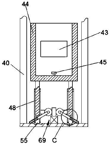
[0019] Reference Figure 1-7 A semiconductor lead electroplating equipment according to an embodiment of the present invention includes a lower base plate 10, an upper base plate 54 is provided on the lower side of the lower base plate 10, and four supports are used between the lower base plate 10 and the upper base plate 54 The rod 40 is fixedly connected. The upper bottom plate 54 is provided with an electroplating bath 44 containing electroplating solution. The inner wall of the electroplating bath 44 is symmetrically fixed with a vibrator 43 that causes the electroplating solution to vibrate. A discharge nail 45 for discharging the electroplating solution is fixed on the inner wall of the ...


PUM


Abstract

The invention discloses semiconductor lead electroplating equipment. An upper bottom plate is arranged on the lower side of a lower bottom plate, the lower bottom plate and the upper bottom plate arefixedly connected through four first supporting rods 1, an electroplating tank for containing an electroplating liquid is arranged on the upper side of the upper bottom plate, vibrators enabling the electroplating liquid to vibrate are symmetrically and fixedly arranged on the left inner wall and the right inner wall of the electroplating tank, discharging nails for discharging the electroplatingliquid are fixedly arranged on the inner wall of the lower side of the electroplating tank, and a lifting device for lifting the electroplating tank upwards is arranged between the electroplating tankand the lower bottom plate. The semiconductor lead electroplating equipment is easy and convenient to operate and low in manufacturing cost, the box for containing the workpieces can move up and downin a mixing mode, the electroplating liquid makes full contact with the workpieces during electroplating, and the electroplating quality is guaranteed.

Description

Technical field [0001] The invention relates to the technical field of semiconductor production, in particular to a semiconductor lead electroplating equipment. Background technique [0002] In the production process of semiconductors, electroplating equipment is used to plate tin on its leads. Traditional semiconductor electroplating equipment includes barrel plating and rack plating. The barrel plating includes a drum and a copper rod horizontally arranged in the drum. The copper rod is energized. As an electroplating cathode, barrel plating is suitable for the electroplating of small parts that cannot or are not suitable for mounting due to factors such as shape and size. Compared with the early plating of small parts using rack plating or basket plating, it saves labor and improves Labor production efficiency, but the existing equipment cannot make the electroplating solution fully contact with the lead wire and cannot process the bubbles remaining in the electroplating solut...

Claims


Application Information

Patent Timeline
Patent Type & Authority Applications(China)
IPC IPC(8): C25D7/12C25D7/06C25D19/00C25D17/02C25D21/00
CPCC25D7/0607C25D7/12C25D17/00C25D17/02C25D21/00
Inventor 不公告发明人
Owner 泰州市昶宇电气科技有限公司
Why Eureka
Try Eureka