Transcritical CO2 closed circulation system

A circulatory system, transcritical technology, applied in the direction of machines/engines, steam engines, mechanical equipment, etc., can solve the problems of low cycle efficiency and narrow operating range of generator/drive units, so as to improve cycle efficiency and avoid unstable unit operation. , the effect of increasing the volume flow of the intake air

Pending Publication Date: 2020-04-07
DONGFANG TURBINE CO LTD
View PDF5 Cites 5 Cited by
  • Summary
  • Abstract
  • Description
  • Claims
  • Application Information

AI Technical Summary

Problems solved by technology

[0004] The present invention aims to provide a transcritical CO 2 Closed loop system to address existing transcritical CO 2 The problem of narrow operating range and low cycle efficiency of generating / driving units

Method used


Image

  • Transcritical CO2 closed circulation system
  • Transcritical CO2 closed circulation system

Examples


Embodiment 1

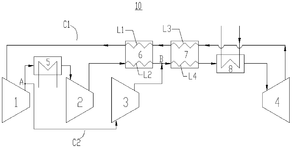
[0036] Please refer to figure 1 , this embodiment provides a transcritical CO 2 A closed cycle system 10 includes a pre-compressor 1 , a main compressor 2 , a re-compressor 3 , a turbine 4 , a cooler 5 , a low-temperature regenerator 6 , a high-temperature regenerator 7 and a heater 8 .

[0037] Wherein, the low temperature regenerator 6 has a first channel and a second channel, the first channel is used as the hot end of the low temperature regenerator 6, and the second channel is used as the cold end of the low temperature regenerator 6; the high temperature regenerator 7 has a third channel and the fourth channel, the third channel is used as the hot end of the high temperature regenerator 7, and the fourth channel is used as the cold end of the low temperature regenerator 6.

[0038] In this embodiment, the outlet of the pre-compressor 1 is connected to the cooler 5, the outlet of the cooler 5 is connected to the inlet of the main compressor 2, the outlet of the main comp...

Embodiment 2

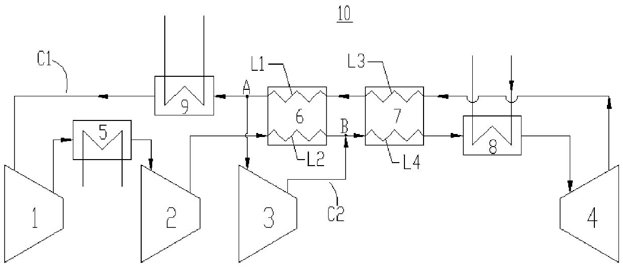
[0050] Please refer to figure 2 , this embodiment provides a transcritical CO 2 The closed circulation system 10 is different from the first embodiment in that the split point A is set between the inlet of the pre-compressor 1 and the outlet of the first channel. Furthermore, in closed CO 2 A second cooler 9 is additionally arranged in series on the circulation circuit C1, and the second cooler 9 is located between the outlet of the first channel and the inlet of the pre-compressor 1; the split point A is set between the outlet of the first channel and the second cooler 9 between the entrances.

[0051] The transcritical CO in this example 2 In addition to the beneficial effects corresponding to the closed circulation system 10 in Embodiment 1,

[0052] It is also possible to adjust the inlet temperature of the pre-compressor 1 by controlling the outlet temperature of the working medium of the additionally provided second cooler 9 to keep it within an appropriate range, t...


PUM


Abstract

The invention belongs to the field of energy conversion, provides a transcritical CO2 closed circulation system and aims at solving the problems of narrow operation range and low circulation efficiency of an existing transcritical CO2 power generation/driving unit. The system comprises a pre-compressor, a main compressor, a re-compressor, a turbine, a cooler, a low-temperature heat regenerator, ahigh-temperature heat regenerator and a heater; the pre-compressor, the main compressor, the re-compressor, the turbine, the cooler, the low-temperature heat regenerator, the high-temperature heat regenerator and the heater are connected to form a closed CO2 circulation loop; a shunting point and a mixing point are arranged on the closed CO2 circulation loop. The inlet of the re-compressor is communicated with the shunting point; the outlet of the re-compressor is communicated with the mixing point; and therefore, a shunting branch is formed; and the shunting branch is shunted out of the outlet of a first channel and converged at the outlet of a second channel. The system has high circulation efficiency. With the system adopted, the operation range of the unit is wide.

Description

technical field [0001] The present invention relates to the field of energy conversion, in particular to transcritical CO 2 Closed circulatory system. Background technique [0002] transcritical CO 2 Closed cycle refers to CO 2 As a circulating working fluid, the highest parameter of the cycle is CO 2 Above the critical point, it is a supercritical state; the lowest parameter of the cycle is in CO 2 Below the critical point, it is liquid. [0003] Since the CO near the critical point 2 The physical properties change drastically, and the outlet parameters of the pre-compressor are close to the critical point. The change of parameters will lead to unstable operation of the unit, especially when the unit changes working conditions, resulting in a narrow operating range of the unit and poor performance under variable conditions. Contents of the invention [0004] The present invention aims to provide a transcritical CO 2 Closed loop system to address existing transcriti...

Claims


Application Information

Patent Timeline
Patent Type & Authority Applications(China)
IPC IPC(8): F01K25/10
CPCF01K25/103
Inventor 廖健鑫田瑞青王文武陈付张粉廖翔
Owner DONGFANG TURBINE CO LTD
Why Eureka
Try Eureka