Ejector refrigerant cycle device

Inactive Publication Date: 2007-07-19
DENSO CORP
View PDF6 Cites 29 Cited by
  • Summary
  • Abstract
  • Description
  • Claims
  • Application Information

AI Technical Summary

Benefits of technology

[0026] According to another aspect of the present invention, an ejector refrigerant cycle device includes: a compressor for compressing and discharging refrigerant; a radiator for radiating heat of high-temperature and high-pressure refrigerant discharged from the compressor; a branch portion for branching a flow of refrigerant on a downstream side of the radiator into a first stream and a second stream; an ejector that includes a nozzle portion for decompressing and expending refrigerant of the first stream from the branch portion, and a refrigerant suction port from which refrigerant is drawn by a high-velocity flow of refrigerant jetted from the nozzle portion; a first decompression means for deco

Problems solved by technology

The inventors of the present application have found that this problem is due to the fact that the refrigerant brought into a super-cooled state after radiating heat in the inner heat exchanger flows into the throttle mechanism.
In other words, the increase in mass flow amou

Method used


Image

  • Ejector refrigerant cycle device
  • Ejector refrigerant cycle device
  • Ejector refrigerant cycle device

Examples


Example

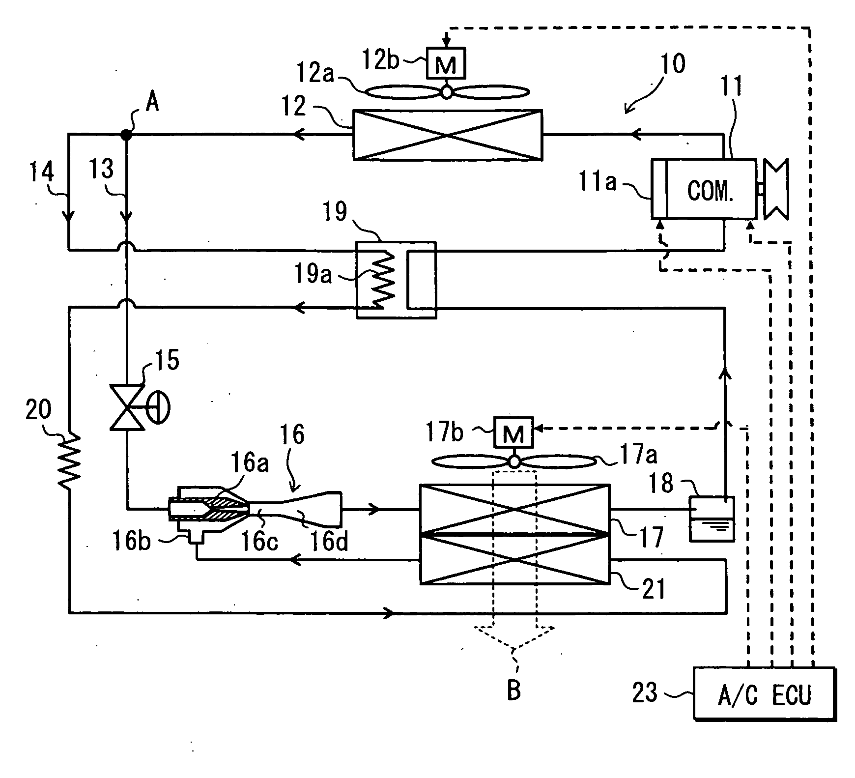
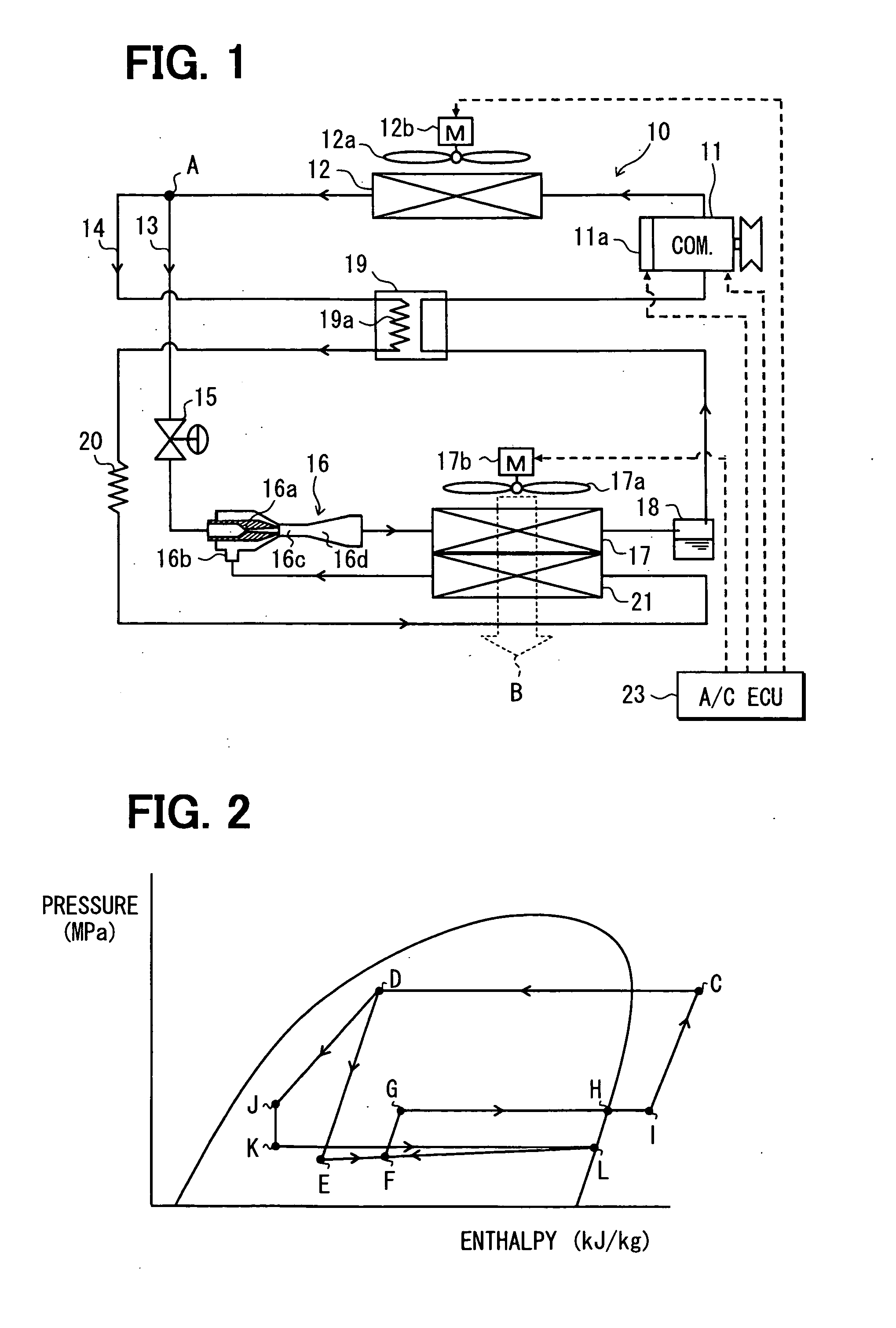
[0052] Referring to FIGS. 1 and 2, a first embodiment of the present invention will be described below. FIG. 1 shows an entire configuration diagram of an example in which an ejector refrigerant cycle device of the first embodiment is applied to a refrigeration device for a vehicle. The refrigeration device for a vehicle of the embodiment is to cool a refrigeration compartment to a very low temperature, for example, about −20° C.

[0053] First, in an ejector refrigerant cycle device 10, a compressor 11 draws, compresses and discharges refrigerant, and has a driving force transmitted thereto from a vehicle running engine (not shown) via a pulley and a belt, thereby being rotatably driven. Moreover, in this embodiment, a well-known swash plate type variable displacement compressor capable of controlling a discharge volume variably and continuously by a control signal from the outside is used as the compressor 11.

[0054] The discharge volume means a geometrical volume of an operating sp...

Example

Second Embodiment

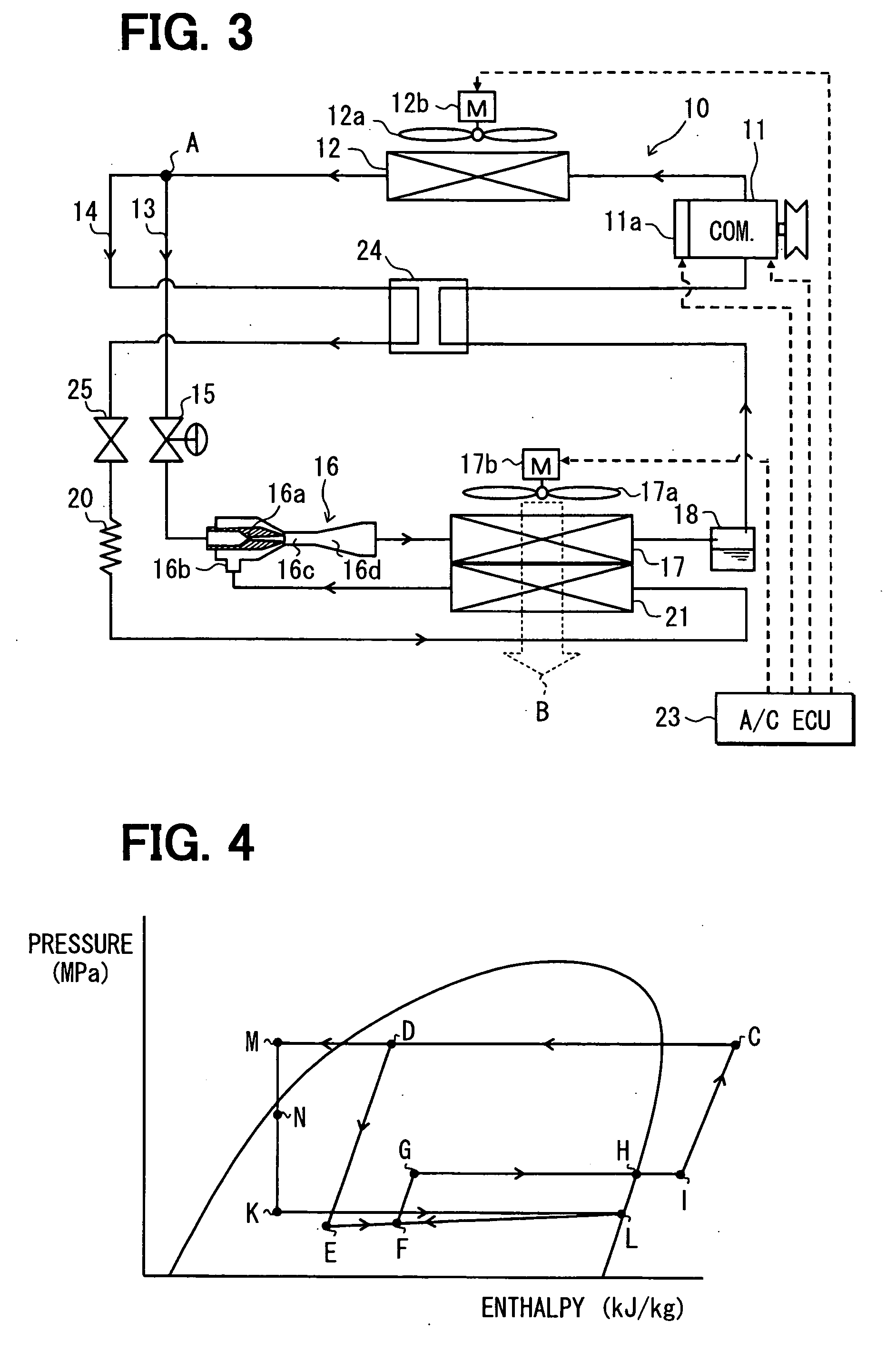
[0095] The above-described first embodiment has explained the adoption of the inner heat exchanger 19 as one example in which the refrigerant passage in the suction-port side piping 14 is constructed of the first fixed throttle 19a. That is, the refrigerant flowing into the inner heat exchanger 19 from the branch portion A is throttled while being cooled. However, in the second embodiment, an inner heat exchanger 24 without having a throttle function is adopted as shown in FIG. 3. The inner heat exchanger 24, whose refrigerant passage is not constructed of the throttle mechanism, has only a function of exchanging heat between the refrigerant on the downstream side of the branch portion A and the refrigerant on the suction side of the compressor 11.

[0096] A first fixed throttle 25 serving as the decompression means for decompressing and expanding the refrigerant to bring it into the vapor-liquid two-phase state is disposed on the downstream side of the inner heat e...

Example

Third Embodiment

[0108] The above-described first embodiment has explained the adoption of the inner heat exchanger 19 as one example in which the refrigerant passage on the downstream side of the branch portion A is constructed of the first fixed throttle 19a. However, in the third embodiment, instead of the inner heat exchanger 19 and the second fixed throttle 20 described in the first embodiment, an inner heat exchanger 26 is used as shown in FIG. 5.

[0109] In one refrigerant passage of the inner heat exchanger 26, through which the refrigerant on the downstream side of the branch portion A passes, there are provided with a first fixed throttle 26a constituted of a capillary tube, and a second fixed throttle 26b arranged on the upstream side of the first fixed throttle 26a. For example, the second fixed throttle 26b is constituted of an orifice or a throttle passage.

[0110] Like the first fixed throttle 19a of the inner heat exchanger 19 in the first embodiment, the first fixed t...


PUM


Abstract

An ejector refrigerant cycle device includes a radiator for radiating heat of high-temperature and high-pressure refrigerant discharged from a compressor, a branch portion for branching a flow of refrigerant on a downstream side of the radiator into a first stream and a second stream, an ejector that includes a nozzle portion for decompressing and expending refrigerant of the first stream from the branch portion, a decompression portion for decompressing and expanding refrigerant of the second stream from the branch portion, and an evaporator for evaporating refrigerant on a downstream side of the decompression portion. The evaporator has a refrigerant outlet coupled to the refrigerant suction port of the ejector. Furthermore, a refrigerant radiating portion is provided for radiating heat of refrigerant while the decompression portion decompresses and expands refrigerant. For example, the refrigerant radiating portion is provided in an inner heat exchanger.

Description

CROSS REFERENCE TO RELATED APPLICATION [0001] This application is based on Japanese Patent Applications No. 2006-005847 filed on Jan. 13, 2006 and No. 2006-214404 filed on Aug. 7, 2006, the contents of which are incorporated herein by reference in its entirety. FIELD OF THE PRESENT INVENTION [0002] The present invention relates to an ejector refrigerant cycle device having an ejector. BACKGROUND OF THE PRESENT INVENTION [0003] JP-A-2005-308380 (corresponding to US 2005 / 0268644 A1) discloses an ejector refrigerant cycle device. In this ejector refrigerant cycle device, a refrigerant flow is branched at a branch portion on the downstream side of a radiator and on the upstream side of a nozzle portion of an ejector into two streams, one of which flows to the nozzle portion, and the other of which flows to a refrigerant suction port of the ejector. [0004] In the ejector refrigerant cycle device of this document, a first evaporator is disposed on the downstream side of a diffuser portion...

Claims


Application Information

Patent Timeline
IPC IPC(8): F25B19/02F25B1/06
CPCF25B5/00F25B40/00F25B2600/2507F25B41/00F25B2341/0011F25B40/02
Inventor IKEGAMI, MAKOTOTAKEUCHI, HIROTSUGUYAMADA, ETSUHISANISHIJIMA, HARUYUKIMATSUI, HIDEYA
Owner DENSO CORP
Why Eureka
Try Eureka