
Gas turbine cycle

Inactive Publication Date: 2006-08-10
SIEMENS ENERGY INC
View PDF18 Cites 18 Cited by
  • Summary
  • Abstract
  • Description
  • Claims
  • Application Information

AI Technical Summary

Benefits of technology

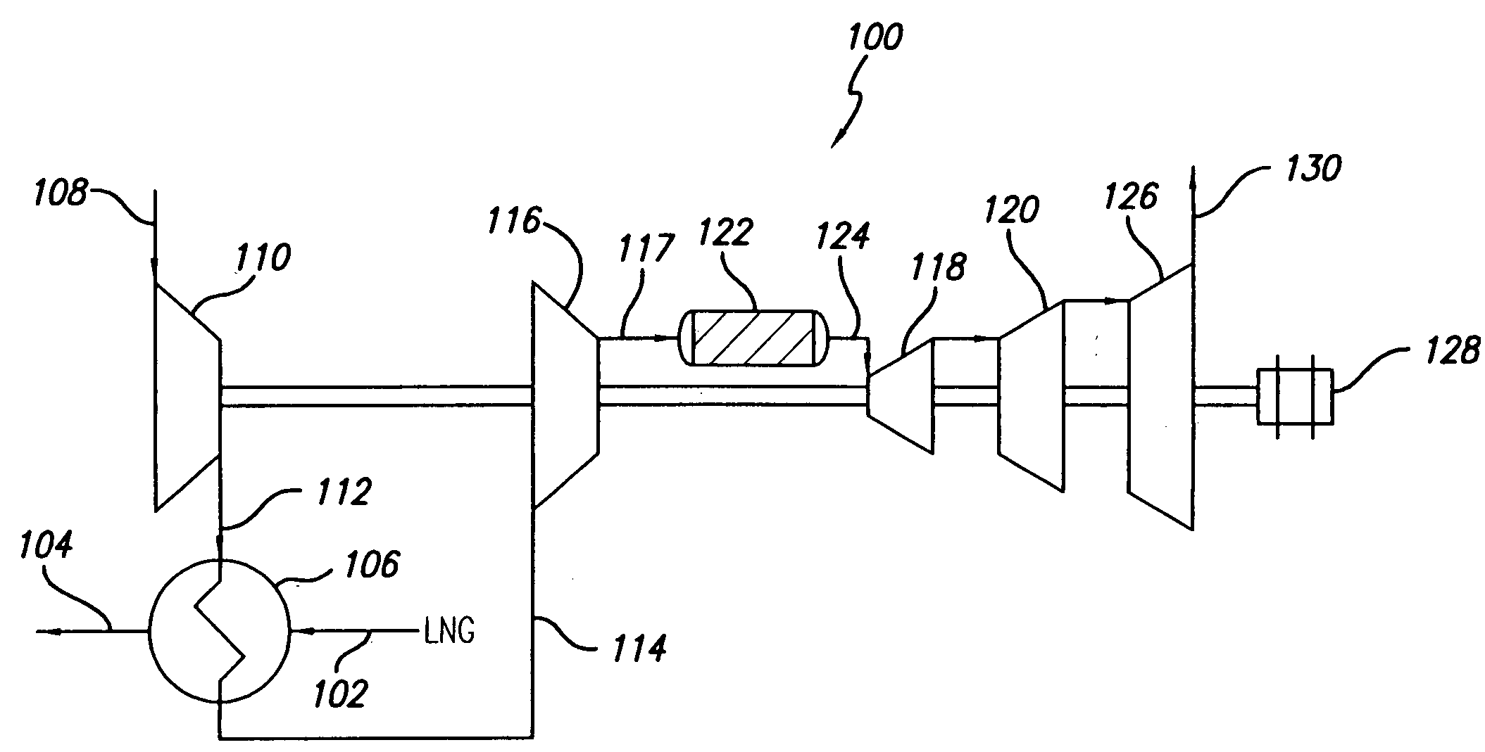
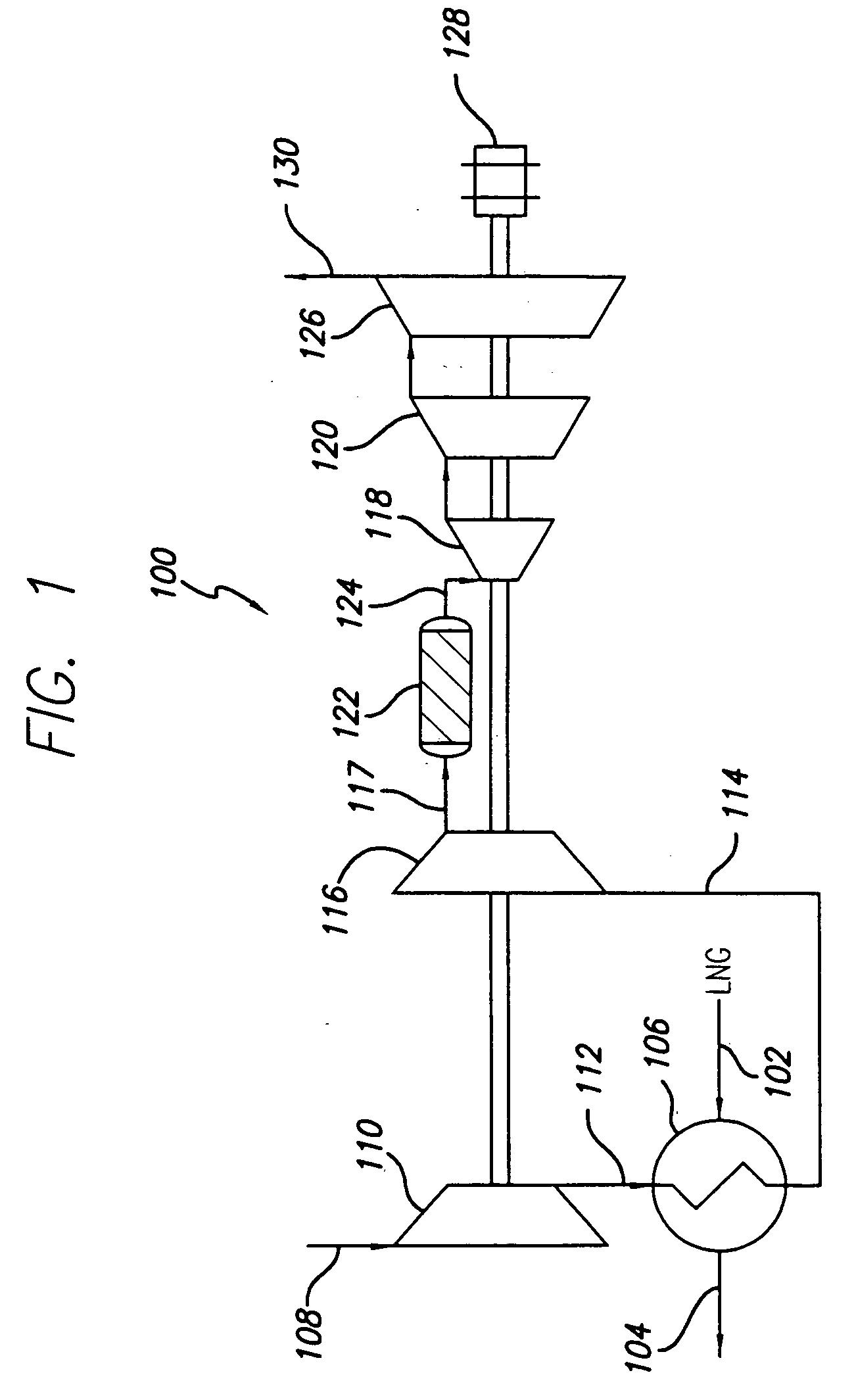
[0013] This present invention provides a gas turbine cycle that utilizes the vaporization of liquefied natural gas (LNG) as an intercooler in an open loop gas turbine cycle. This process offers the potential to increase gas turbine cycle efficiencies while providing a convenient system for vaporizing LNG. The systems of the present invention permit the vaporization of LNG using air that has been compressed in a low-pressure compressor, with the resulting cooled air being easier to compress and / or having fewer contaminants therein for compression in a high-pressure compressor. As the air is easier to compress, less energy is needed to operate the high-pressure compressor, thereby increasing the efficiency of the system. In one embodiment, a portion of the vaporized natural gas may be used as the combustion fuel for the gas turbine system.

Problems solved by technology

In the meantime, a gas turbine has the disadvantage of decreasing in output with increasing atmospheric temperature.
Unfortunately, atmospheric temperature is highest in the afternoon in summer when the electric power consumption and demand can be high due to increase in operation of equipment such as air conditioners.
This prevents high efficiency of the gas turbine cycle for power generation.
Although coolers, refrigeration systems and fogging devices are effective in facilitating high power output from a gas turbine engine on a hot day, these systems and devices also typically require water pumps, pressurized air for aspiration, and other components which increase the engine cost, including maintenance cost.
In addition, such systems and devices require water clean-up.
Although many suggestions have been made and some installations have been built to utilize the large cold potential of the LNG, in most receiving terminals the cold potential is wasted and the LNG is simply heated with a large flow of sea water that has to be applied in such a manner as to avoid ice formation.
However, it has been found that even with relatively simple cycles only a small part of the available cold potential can be utilized.

Method used


Image

  • Gas turbine cycle
  • Gas turbine cycle

Examples


Embodiment Construction

[0017] The present invention is more particularly described in the following description and examples that are intended to be illustrative only since numerous modifications and variations therein will be apparent to those skilled in the art. As used in the specification and in the claims, the singular form “a,”“an,” and “the” may include plural referents unless the context clearly dictates otherwise. Also, as used in the specification and in the claims, the term “comprising” may include the embodiments “consisting of” and “consisting essentially of.”

[0018] The present invention provides an open loop gas turbine system that utilizes the vaporization of liquefied natural gas as an intercooler between two compressors of a gas turbine. The present invention offers the potential for improved efficiencies. The present invention vaporizes LNG using air coming from a low-pressure compressor, with the resulting cooled air being easier to compress in the high-pressure compressor. As the air i...


PUM


Abstract

A gas turbine cycle that utilizes the vaporization of liquefied natural gas as an intercooler in an open loop gas turbine system. The system provides an increase in gas turbine cycle efficiencies while providing a convenient system for vaporizing liquefied natural gas. The systems and methods of the present invention permit the vaporization of liquefied natural gas using air that has been compressed in a first compressor, with the resulting cooled air being easier to compress and / or having fewer contaminants therein for compression in a second compressor. As the air is easier to compress, less energy is needed to operate the second compressor, thereby increasing the efficiency of the system. Additionally, unlike prior art systems that use water as an intercooler, no additional equipment is needed to cool the vaporized natural gas, such as cooling towers.

Description

FIELD OF THE INVENTION [0001] This invention is directed generally to turbine systems, and more particularly to open loop gas turbine systems utilizing the thermodynamic heat sink potential of liquefied natural gas. BACKGROUND [0002] One method of thermal power generation is by gas turbines that are powered by the combustion of some fuel, and it may be applied to power plants having a capacity up to several hundreds of thousand of kilowatts. Additionally, there are methods of thermal power generation that are commonly called combined cycle power generation. These methods are based on a gas turbine cycle and a steam cycle in combination. The steam cycle is powered by the exhaust energy from the gas turbine cycle. They offer an advantage of being started and stopped easily and allow easy control for load variation. Moreover, these combined methods of power generation are more efficient than the gas turbine cycle or ordinary steam power generation alone. [0003] Gas turbine engines gene...

Claims


Application Information

Patent Timeline
IPC IPC(8): F02C7/143
CPCF02C6/18F02C7/143F02C7/16
Inventor MCQUIGGAN, GERARD
Owner SIEMENS ENERGY INC
Learn More