Control method and device for variable valve timing system of Miller cycle engine

A valve timing and Miller cycle technology, applied in engine control, engine components, combustion engines, etc., can solve the problems of small valve lift and wrap angle, poor acceleration loading capacity, etc., and achieve the effect of improving acceleration loading capacity

Active Publication Date: 2020-04-07
SAIC MOTOR
View PDF9 Cites 7 Cited by
  • Summary
  • Abstract
  • Description
  • Claims
  • Application Information

AI Technical Summary

Problems solved by technology

However, in transient conditions, due to the small valve lift and wrap an

Method used


Image

  • Control method and device for variable valve timing system of Miller cycle engine
  • Control method and device for variable valve timing system of Miller cycle engine
  • Control method and device for variable valve timing system of Miller cycle engine

Examples


Embodiment Construction

[0052] The specific implementation of the application will be further described below in conjunction with the accompanying drawings. The implementation of the application is not limited by the following methods, as long as the method concept and technical solutions of the application are adopted. The direct application of ideas and technical solutions to other occasions is within the protection scope of this application.

[0053]In order to facilitate understanding of the technical solution of the present application, the background technology of the technical solution of the present application is briefly described below.

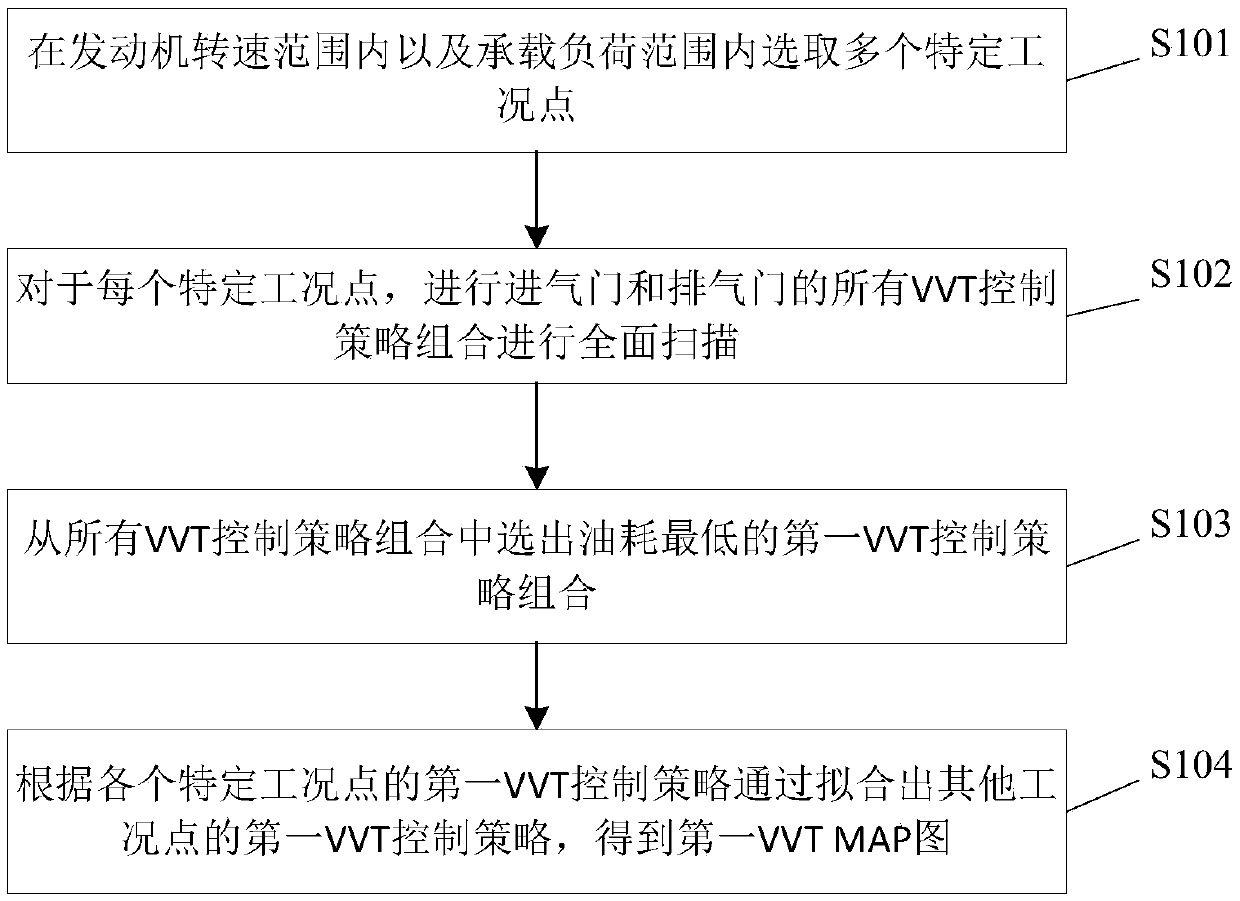
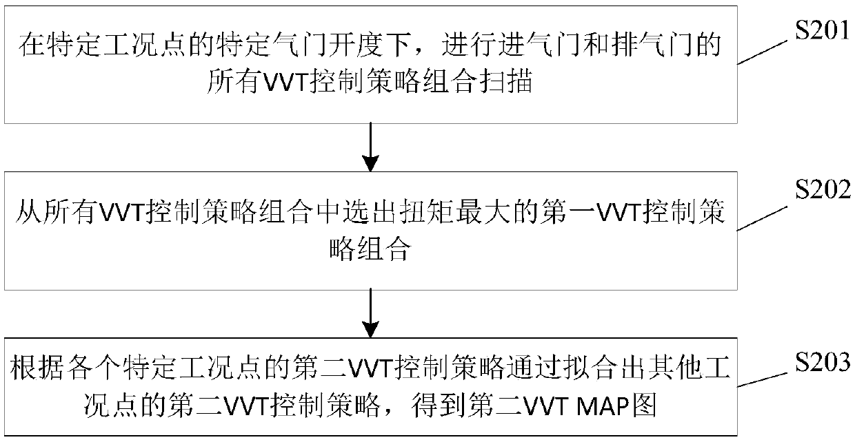
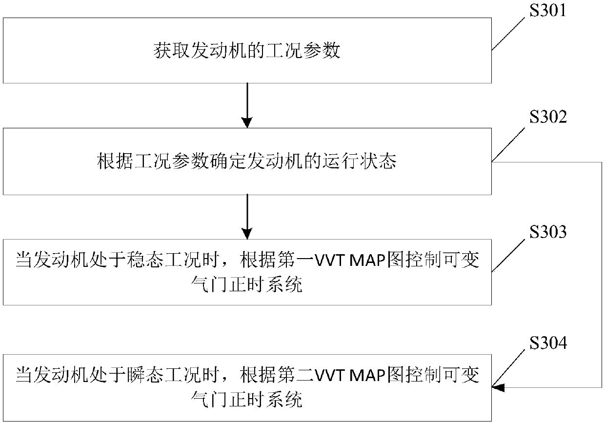
[0054] Based on the problems existing in the Miller cycle engine in the prior art described in the background technology, the inventor has studied and proposed a control method for the variable valve timing system of the Miller cycle engine. First, the operating condition parameters of the engine are obtained , determine the current operating state of the ...


PUM


Abstract

The invention provides a control method and device for a variable valve timing system of a Miller cycle engine. In the control method, a first VVT MAP taking economical efficiency as a target and a second VVT MAP taking dynamic property as a target are previously demarcated, and when the engine is in a running state under a steady-state working condition, the variable valve timing system is controlled by virtue of the first VVT MAP, and the economical efficiency of the engine is realized; and when the engine is in a running state under a transient accelerated loading working condition, the variable valve timing system is controlled by virtue of the second VVT MAP, and the dynamic property of the engine is realized, and in this way, when the working conditions of the engine are different, the different VVT MAPs are chosen to control the variable valve timing system. Compared with the purpose of realizing the economical efficiency of the engine in the prior art, the control method and device for the variable valve timing system of the Miller cycle engine give consideration to the economical efficiency and the dynamic property of the engine simultaneously, and improves the acceleratedloading capacity under the transient working condition of the engine.

Description

technical field [0001] The present application relates to the technical field of Miller cycle engines, in particular to a control method and device for a variable valve timing system of a Miller cycle engine. Background technique [0002] Compared with the battery as the power source, the gasoline engine as the power source can realize the long-distance driving of the car. [0003] Most of the existing gasoline engines use the Otto cycle, the valve lift and wrap angle are relatively large, resulting in the highest thermal efficiency of the gasoline engine is only 40%, and more than 30% of the energy is taken away by the exhaust, so the Otto cycle gasoline The engine has problems such as large pumping loss and poor economy. [0004] The valve lift and wrap angle of the Miller cycle engine are small, and the engine load is controlled by changing the closing angle of the intake valve, thereby reducing the pumping loss of the engine under partial load, and solving the problem o...

Claims


Application Information

Patent Timeline
IPC IPC(8): F01L1/344F02D13/02
CPCF01L1/34409F02B2275/32F02D13/0215Y02T10/12
Inventor 王绍明程传辉徐政杨琦刘旭张敬晨
Owner SAIC MOTOR
Why Eureka
Try Eureka