Portable fan
A fan and portable technology, applied in electromechanical devices, electrical components, liquid fuel engines, etc., can solve the problem of not meeting the needs of multi-target, multi-directional, large-angle air supply, etc., to achieve compact structure, reduce occupied space, The effect of improving stability
- Summary
- Abstract
- Description
- Claims
- Application Information
AI Technical Summary
Problems solved by technology
Method used
Image

Examples
Embodiment 1
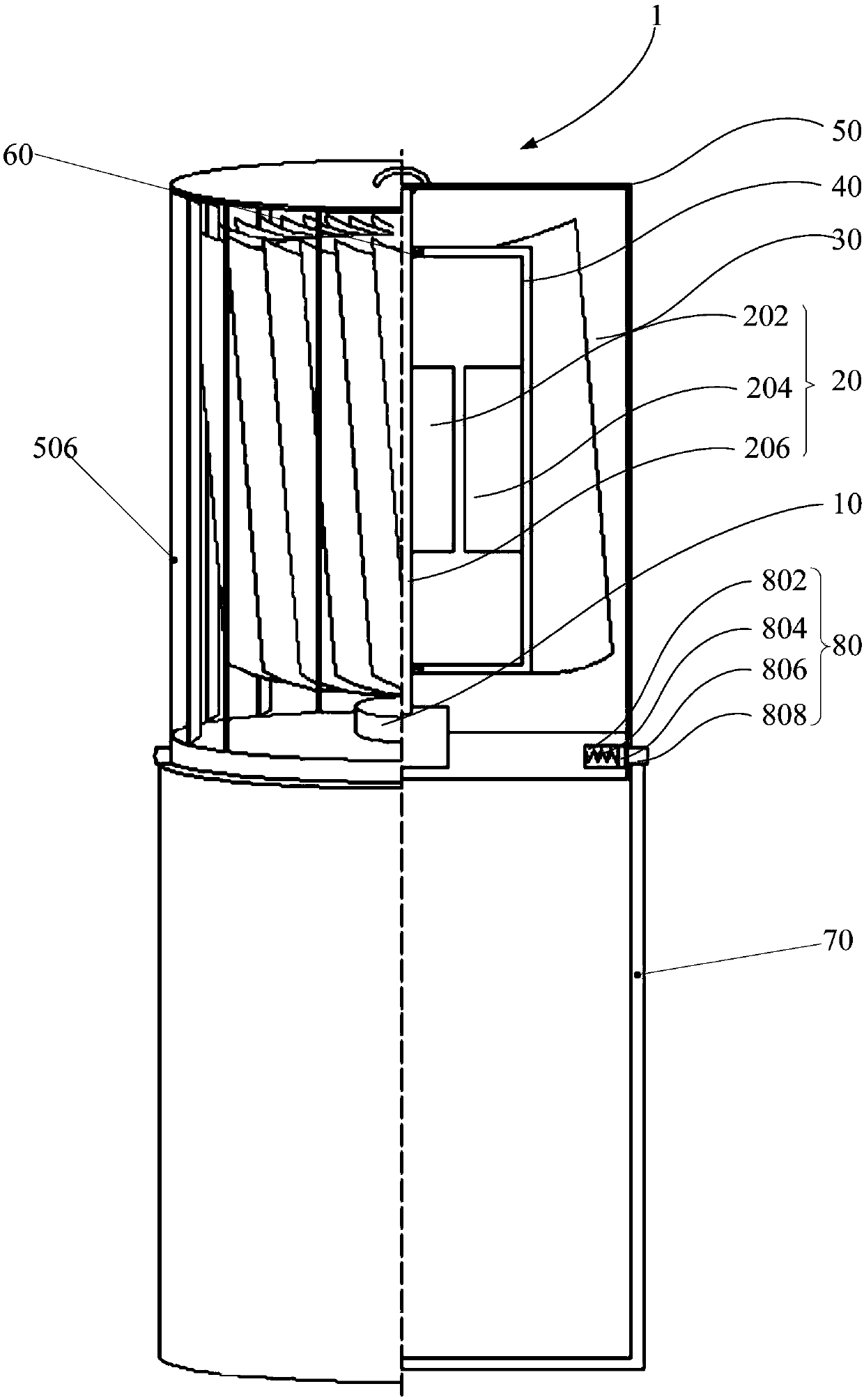
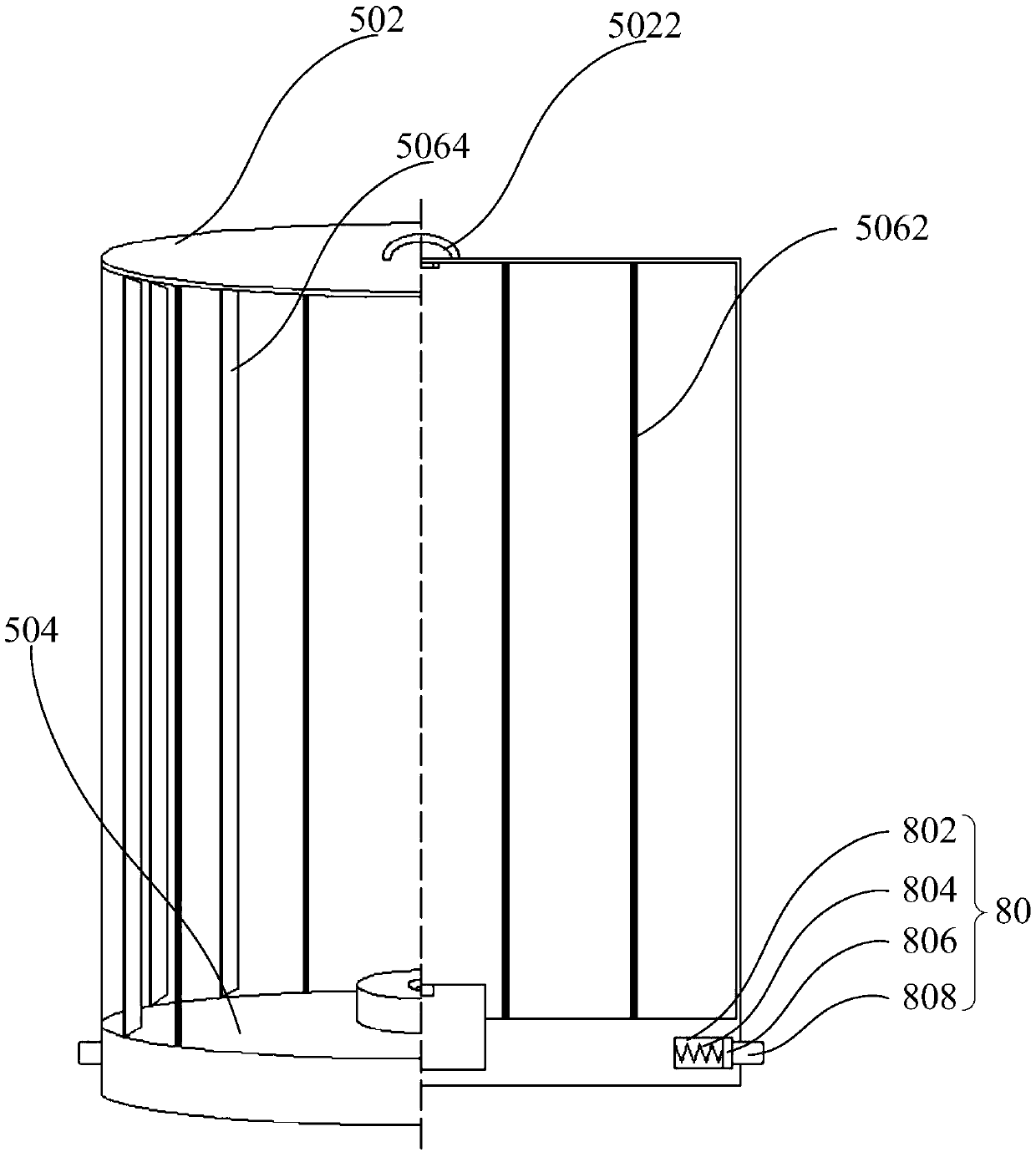
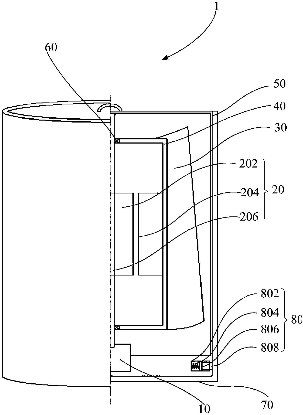
[0080] Such as Figure 1 to Figure 3 As shown, in the above embodiment, preferably, the stopper 80 is installed at a designated position of the fan main body in the horizontal direction, and the stopper 80 includes in turn from the inside to the outside in the radial direction: Barrel section 802; elastic body 804, one end of the elastic body 804 is connected to the inner barrel bottom of the limiting barrel section 802; a limiting movable block 806 is connected to the other end of the elastic body 804, and the limiting block can fill the limiting barrel section 802 , and move back and forth in the limiting cylinder section 802; abut against the limiting block 808, and connect with the side of the limiting movable block 806 that is not connected with the elastic body 804, wherein, after the main body of the fan is accommodated in the accommodating cavity, the elastic body 804 In the compressed state, the abutting limit block 808 can abut against the inner wall of the housing 7...
Embodiment 2
[0090] In this embodiment, by opening a limit hole on the housing case 70 so that the abutment limit block 808 protrudes out of the limit hole, and by plugging between the abutment limit block 808 and the limit hole, Limiting the main body of the fan further improves the reliability of the limiting.
[0091] In any of the above embodiments, preferably, one of the outer wall of the fan main body and the inner wall of the housing 70 is provided with an axial guide groove, and the other is provided with a guide rib matching the guide groove.
[0092] In this embodiment, the fluency when the fan main body is pushed into or pulled out of the housing case 70 is further improved by providing guide grooves and guide ribs that cooperate with each other.
[0093] Such as image 3 As shown, in any of the above-mentioned embodiments, preferably, the fan body further includes: a base disposed at the bottom of the motor 20 for supporting the motor 20 .
[0094] as shown in the picture fi...
Embodiment 3
[0119] Such as figure 1 As shown, in any of the above embodiments, preferably, when the motor 20 is an outer rotor motor 20, the inner wall of the blade frame 40 is fixedly connected to the outer wall of the motor rotor 204, wherein the motor shaft 206 is fixed shaft, and is fixedly connected with the base 10.
[0120] In this embodiment, the outer side wall of the motor rotor 204 of the outer rotor motor 20 can be directly fixedly connected to the inner side wall of the fan blade frame 40. On the one hand, it meets the requirement of using the outer rotor motor 20 as a power source device, and on the other hand On the one hand, through the contact connection between the side walls, the connection area can be increased, thereby improving the stability of the fan blade 30 during rotation.
PUM
 Abstract
Description
Claims
Application Information
 - R&D
- Intellectual Property
- Life Sciences
- Materials
- Tech Scout
- Unparalleled Data Quality
- Higher Quality Content
- 60% Fewer Hallucinations
Browse by: Latest US Patents, China's latest patents, Technical Efficacy Thesaurus, Application Domain, Technology Topic, Popular Technical Reports.
© 2025 PatSnap. All rights reserved.Legal|Privacy policy|Modern Slavery Act Transparency Statement|Sitemap|About US| Contact US: help@patsnap.com