Underwater hose safe disengaging device

A disengagement device and safe technology, applied in the direction of hose connection device, fluid pressure actuating device, fluid pressure actuating system safety, etc., can solve the problems of high risk, difficult operation, damage of water surface support system, etc., to achieve stable and reliable The effect of snapping

Pending Publication Date: 2020-04-07
CHINA MINMETALS CHANGSHA MINING RES INST
View PDF1 Cites 4 Cited by
  • Summary
  • Abstract
  • Description
  • Claims
  • Application Information

AI Technical Summary

Problems solved by technology

[0002] Underwater operations such as deep-sea mining, river channel dredging, and river bottom sandstone mining usually involve underwater hose transportation operations; however, in complex underwater environments, sometimes there will be some unforeseen emergencies , it is necessary to separate the surface support system from the underwater equipment urgently to ensure the safety of the surface support system. If the hose delivery pipeline cannot be separated in time, the surface support system will be destroyed, and in severe cases, it will cause casualties and huge property losses.
[0003] At present, in the process of underwater hose operation, when an abnormal situation occurs, the operator directly separates by destroying the conveying hose, which is difficult to operate and has high risks; while the hose separation device used in the land environment is mostly manual separation, such as the announcement No. CN202228831U patent proposed automobile power steering pump test quick change joint, including steel ball, circular circlip, spring; the quick change joint body and the outer joint head are connected together and locked with the lock nut, and the left end of the lock nut is set on the outside On the outer peripheral surface of the connector, the inner end surface is clamped on the shoulder of the outer connector, the right end of the lock nut is threaded to connect the quick-change connector body, the inner hole of the quick-change connector is set on the right end of the outer connector, and the outer connector in the inner hole of the quick-change connector There is a gasket on the outside of the right end, a spring is set on the outer circumference of the right end of the quick change joint body, and a quick change sleeve is set outside the spring, the left end of the spring is clamped on the shoulder of the quick change joint body, and the right end is clamped on the inner end surface of the quick change sleeve Above, the right end face of the quick-change sleeve is limited by a circular circlip, which is installed in the circular groove of the quick-change joint body, and the symmetrical round holes corresponding to the springs on the quick-change joint body are respectively equipped with steel balls and steel balls. The exposed outer edge of the ball is movably connected to the spring, and the exposed inner edge of the steel ball is placed in the inner hole of the quick-change joint body. This technology uses the spring to limit the radial movement of the steel ball to block the oil inlet pipe, but it cannot be realized in the water. The function of automatic separation under

Method used


Image

  • Underwater hose safe disengaging device
  • Underwater hose safe disengaging device
  • Underwater hose safe disengaging device

Examples


Embodiment 1

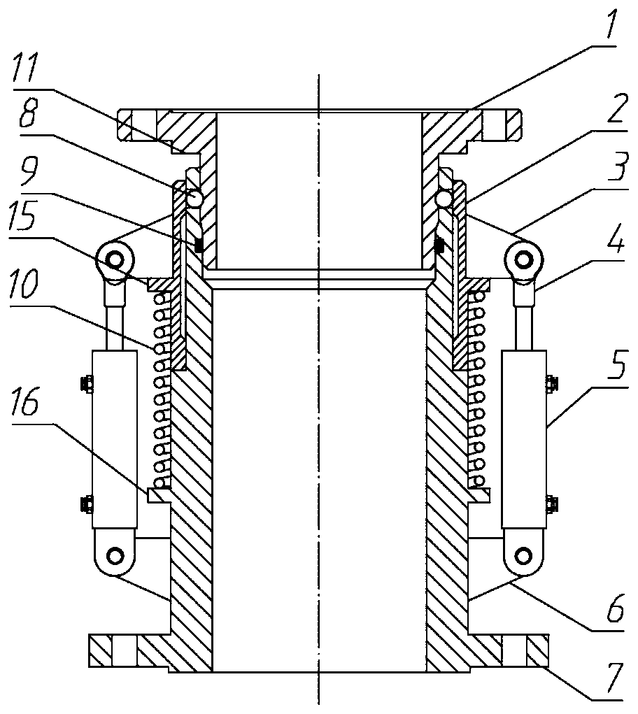
[0030] Such as Figure 1 to Figure 2 As shown, an underwater hose safety disconnection device includes a male joint 1, a slip ring 2, a first support 3, an earring 4, an oil cylinder 5, a second support 6, a female joint 7, a steel ball 8, and a seal 9. Compression elastic member 10 and linear drive device 12;

[0031] The male joint 1 and the female joint 7 are hollow cylinders;

[0032] One end of the male connector 1 is a flange structure, which is connected to the flange of the hose;

[0033] A stepped surface 11 is provided on the outer wall of the male joint 1 close to the flange mounting surface;

[0034] The other end of the male connector 1 is sleeved in the central hole of the female connector 7;

[0035] The other end of the female joint 7 is a flange structure, which is connected with the flange interface of the working equipment;

[0036] The material in the hose enters the operating equipment through the central holes of the male joint 1 and the female joint ...

Embodiment 2

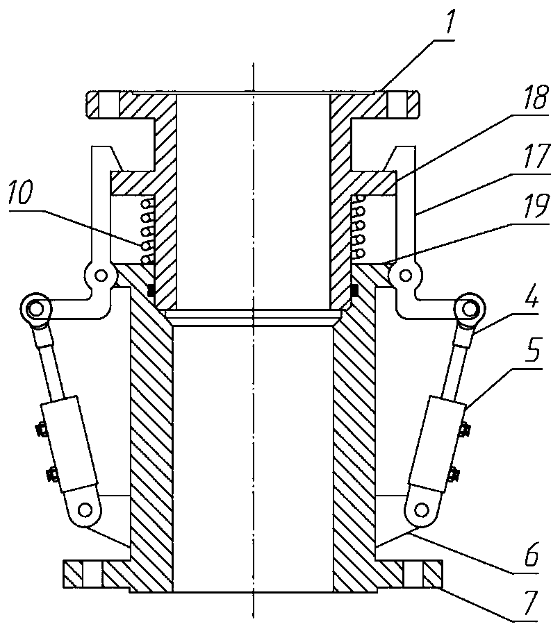
[0064] Such as Figure 3 to Figure 4 As shown, in this embodiment, claws are used to securely clamp the male joint 1 and the female joint 7 .

[0065] Specifically, an underwater hose safety detachment device, including a male joint 1, a female joint 7, a sealing member 9, a compression elastic member 10, a swing arm 17 and a linear drive device 12;

[0066] The outer wall of the male joint 1 is provided with a third step 18;

[0067] The end of the female joint 7 opposite to the flange is provided with a fourth step 19;

[0068] Several swing arms 17 are arranged circumferentially along the outer wall of the female joint 7;

[0069] The swing arm 17 is an L-shaped flat plate, and its middle position is hinged with the fourth step 19;

[0070] The upper end of the swing arm 17 is provided with a claw, and the claw hooks the upper surface of the third step 18;

[0071] The lower end of the swing arm 17 is bent outward at 90 degrees, and its end is hinged to the movement ter...


PUM


Abstract

The invention discloses an underwater hose safe disengaging device. A male connector and a female connector are reliably connected in a clamping mode and a linear driving unit is adopted to drive a clamping device to achieve a function of automatic disengaging of the underwater male connector and the female connector, and major safety accidents are prevented from happening when emergency disengaging is needed under an abnormal condition. A hydraulic lock is arranged on an oil liquid control loop, and the male connector and the female connector can be effectively ensured to be stably and reliably connected in a clamped mode when a hydraulic system has no power. In addition, a parallel control loop provided with the hydraulic lock is arranged on the oil liquid control loop, and the hydrauliclock on the parallel loop is opened through pressurization of a manual pump under the condition that the system loses power so that separation of the male connector and the female connector is achieved.

Description

technical field [0001] The invention relates to the technical field of underwater machinery, in particular to an underwater hose safety detachment device. Background technique [0002] Underwater operations such as deep-sea mining, river channel dredging, and river bottom sandstone mining usually involve underwater hose transportation operations; however, in complex underwater environments, sometimes there will be some unforeseen emergencies , it is necessary to urgently separate the surface support system from the underwater equipment to ensure the safety of the surface support system. At this time, if the hose delivery pipeline cannot be separated in time, the surface support system will be destroyed, and in severe cases, it will cause casualties and huge property losses. [0003] At present, in the process of underwater hose operation, when an abnormal situation occurs, the operator directly separates by destroying the conveying hose, which is difficult to operate and has...

Claims


Application Information

Patent Timeline
IPC IPC(8): F16L33/16F16L37/62F16L37/23F16L37/127F15B13/01F15B13/044F15B20/00
CPCF15B13/01F15B20/002F15B2013/0448F16L33/16F16L37/1205F16L37/23F16L37/62
Inventor 吴鸿云吴友华徐俊杰李翀陈秉正
Owner CHINA MINMETALS CHANGSHA MINING RES INST
Why Eureka
Try Eureka