
High-voltage interlocking system and detection method thereof

A high-voltage interlock and detection method technology, applied in the field of electric power, can solve problems such as high-voltage interlock system falsely reporting faults, high-voltage interlock systems unable to determine faults, and reducing the reliability of high-voltage interlock systems

Active Publication Date: 2020-04-07
CONTEMPORARY AMPEREX TECH CO
View PDF7 Cites 14 Cited by
  • Summary
  • Abstract
  • Description
  • Claims
  • Application Information

AI Technical Summary

Problems solved by technology

If the signal source is disturbed or damaged, the high-voltage interlock system may falsely report a fault or the high-voltage interlock system cannot determine the fault, thereby reducing the reliability of the high-voltage interlock system

Method used


Image

  • High-voltage interlocking system and detection method thereof
  • High-voltage interlocking system and detection method thereof
  • High-voltage interlocking system and detection method thereof

Examples


Embodiment Construction

[0025] Features and exemplary embodiments of various aspects of the invention will be described in detail below. In the following detailed description, numerous specific details are set forth in order to provide a thorough understanding of the present invention. It will be apparent, however, to one skilled in the art that the present invention may be practiced without some of these specific details. The following description of the embodiments is only to provide a better understanding of the present invention by showing examples of the present invention. The present invention is by no means limited to any specific configurations and algorithms presented below, but covers any modification, substitution and improvement of elements, components and algorithms without departing from the spirit of the invention. In the drawings and the following description, well-known structures and techniques have not been shown in order to avoid unnecessarily obscuring the present invention.

...


PUM


Abstract

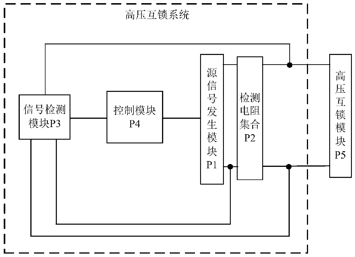
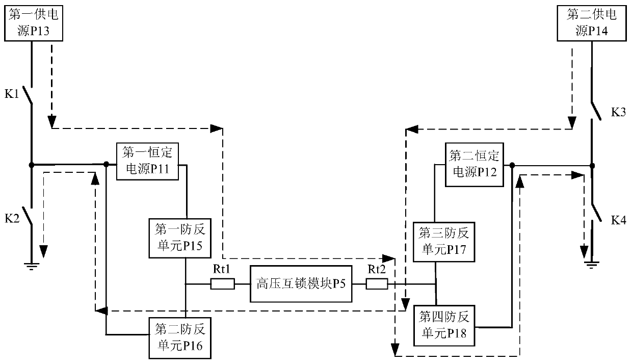
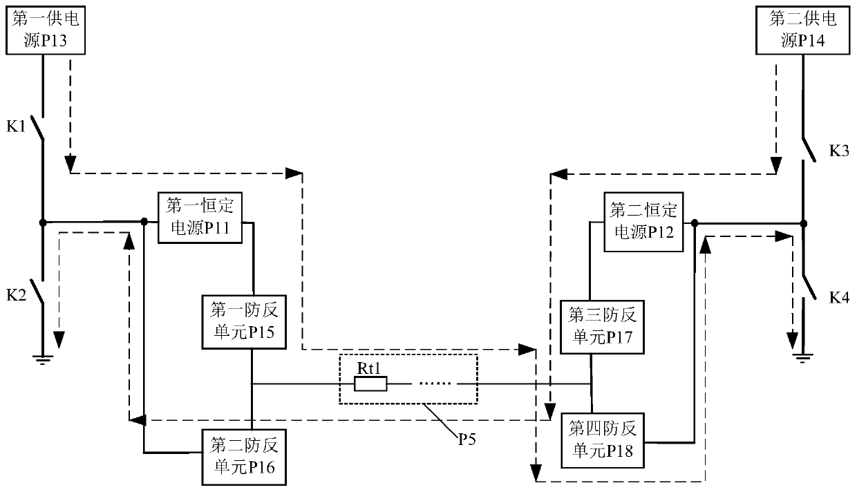
The invention provides a high-voltage interlocking system and a detection method thereof, and relates to the technical field of electric power. In the high-voltage interlocking system, if it is determined that both the first constant power supply and the second constant power supply do not fail, the control module inputs a first driving signal to the source signal generation module, controls to output an alternating-current electric signal. If one of the first constant power supply and the second constant power supply is determined to have a fault, a second driving signal is input to the source signal generation module, a direct-current electric signal is controlled to be output, a detection result signal is received, and the fault of the high-voltage interlocking module is determined according to the detection result signal. The source signal generation module controls the first constant power supply and the second constant power supply to be alternately in a working state according to the first driving signal, and controls the power supply which does not fail to be in the working state continuously according to the second driving signal. The signal detection module outputs a detection result signal according to the electric signal of the detection resistor set. By means of the technical scheme, the reliability of the high-voltage interlocking system can be improved.

Description

technical field [0001] The invention belongs to the technical field of electric power, and in particular relates to a high-voltage interlock system and a detection method thereof. Background technique [0002] With the rapid development of new energy vehicles, the safety of new energy vehicles has become a focus of attention. New energy vehicles rely on high voltage and high current to power the car. Therefore, the high-voltage interlock system in high-voltage safety is very important in the high-voltage loop monitoring system. [0003] The high-voltage interlock system is used to monitor the integrity of the connection between various high-voltage components in the new energy vehicle to ensure that the new energy vehicle can run in a safe state. The high-voltage interlock system has a signal source that generates a signal, and the signal source provides a signal for fault detection of the high-voltage interlock system. If the signal source is disturbed or damaged, the hig...

Claims


Application Information

Patent Timeline
Patent Type & Authority Applications(China)
IPC IPC(8): G01R31/28
CPCG01R31/2827G01R31/2829
Inventor 代伟傅焱辉刘宇李前邓
Owner CONTEMPORARY AMPEREX TECH CO
Learn More