
Dynamic vision sensor

A visual sensor and visual sensing technology, applied in the direction of TV, color TV, color TV parts, etc., can solve the problems that affect the identification of key information of the scene, the advantages of data collection are difficult to show, and affect driving safety, etc., to reduce The effect of background information

Active Publication Date: 2020-04-07
HUAWEI TECH CO LTD
View PDF5 Cites 6 Cited by
  • Summary
  • Abstract
  • Description
  • Claims
  • Application Information

AI Technical Summary

Problems solved by technology

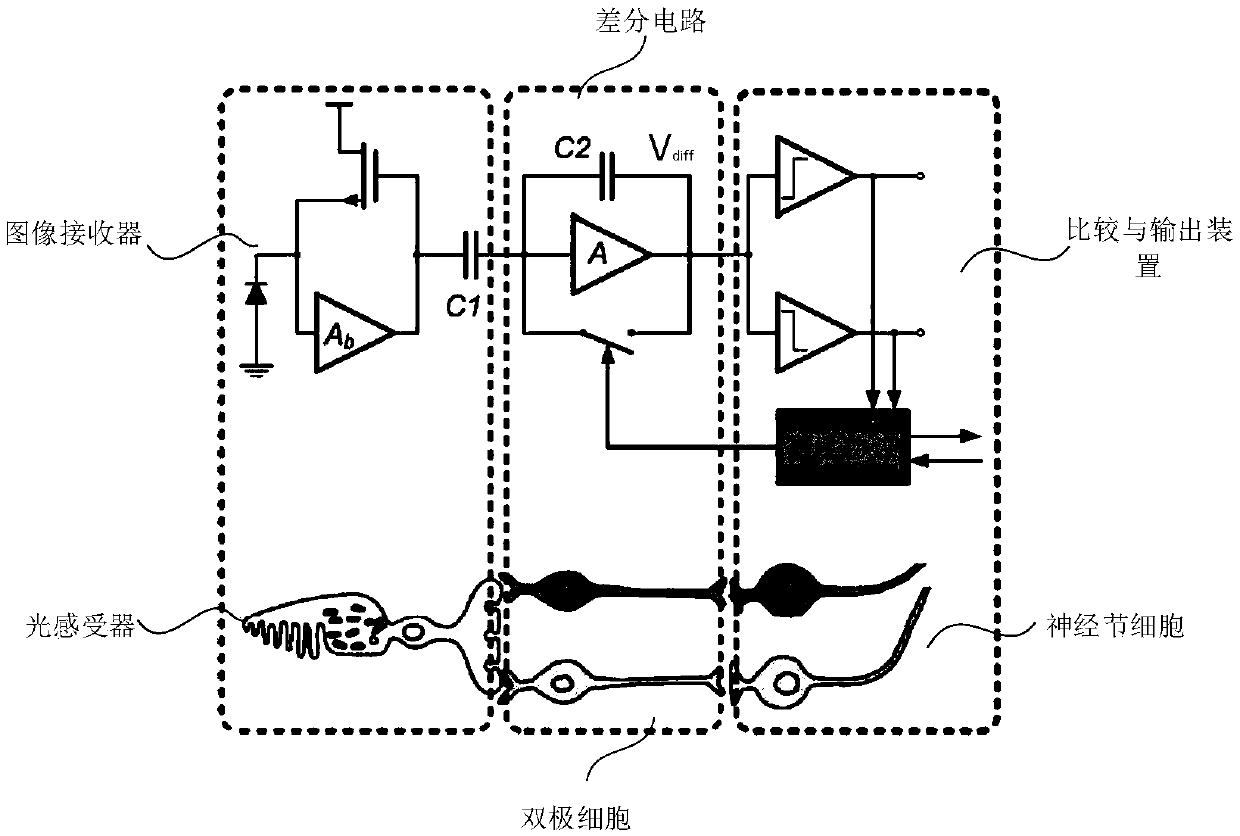
[0008] However, the existing DVS uses a first-order differential circuit to capture moving images, which is very sensitive to brightness changes
When the imaging device itself is also moving, it means that every pixel in the entire picture will feel the brightness change, and the captured picture is very noisy, it is difficult to filter out the background interference, which affects the recognition of key information in the scene; at the same time, asynchronous The advantage of the output cannot be reflected, which may cause bus congestion
For example, if the existing DVS imaging equipment is used for road condition detection of the automatic driving system, and the road conditions and surrounding scenery are continuously recorded during driving, if an obstacle suddenly appears in front, the image captured by the camera will be that the obstacle is mixed in the surrounding scene Panorama, it is difficult for machines to distinguish and identify obstacles, which is prone to safety hazards
In addition, when the imaging device itself is moving, since the brightness of each pixel will change, all pixels will continue to collect information, making it difficult to show the original advantage of reducing the amount of data collected, and it may also cause channel congestion. Causes poor communication and affects driving safety

Method used


Image

  • Dynamic vision sensor
  • Dynamic vision sensor
  • Dynamic vision sensor

Examples


Embodiment Construction

[0048] The technical solutions in the embodiments of the present invention will be clearly and completely described below in conjunction with the drawings in the embodiments of the present invention.

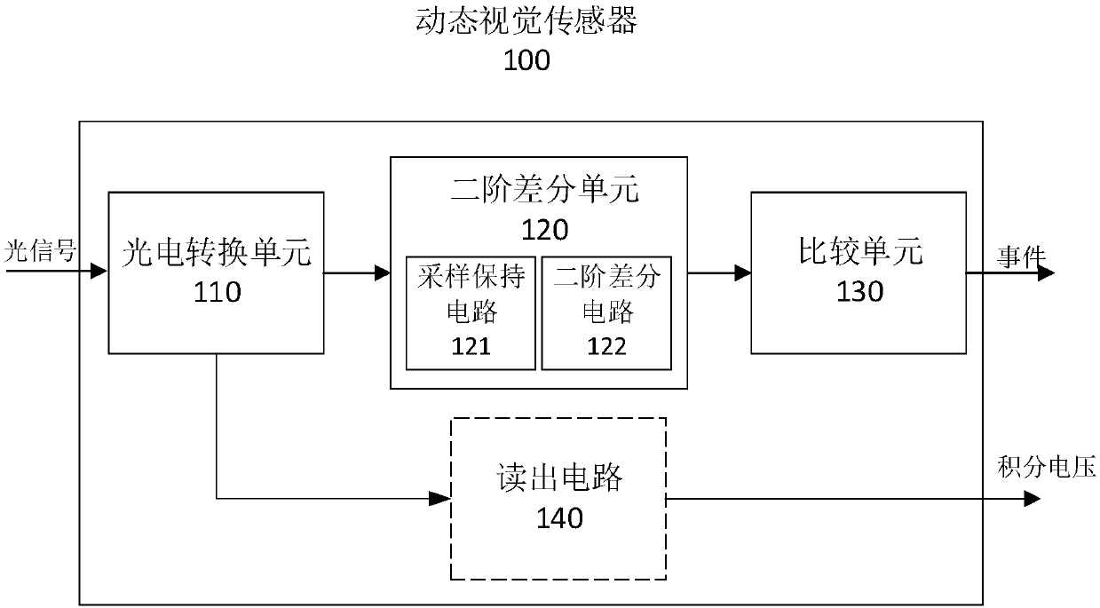
[0049] see image 3 , is a schematic diagram of a logical structure of a possible embodiment of the dynamic vision sensor of the present invention. The dynamic vision sensor 100 includes a photoelectric conversion unit 110 , a second-order differential unit 120 and a comparison unit 130 , wherein the second-order differential unit includes a sample-and-hold circuit 121 and a second-order differential circuit 122 . In some possible implementations, the dynamic vision sensor 100 may also include a readout circuit 140 . In some possible implementation manners, the sample and hold circuit 121 may also be considered as a component of the photoelectric conversion unit 110 . For the convenience of description, this embodiment only describes the sample-and-hold circuit 121 belonging t...


PUM


Abstract

The invention provides a dynamic vision sensor. The sensor converts an optical signal into an electric signal through a photoelectric conversion unit, generates a photosensitive voltage, performs second-order difference on the photosensitive voltage through a second-order difference circuit, and generates a second-order event signal according to a second-order difference result. A camera comprising the sensor is capable of generating an image from the second order event signal, the image characterizing a change in the rate of change of light, thus reducing redundant background information whenthe camera is moving.

Description

technical field [0001] The invention relates to the technical field of image collection, in particular to a device and method for dynamic visual image collection. Background technique [0002] With the development of society, the field of image acquisition has higher and higher requirements for the quality of collected images. A general camera can collect 25-30 frames per second, and its frame rate is not enough to support the collection of images of high-speed moving objects. At present, there are mainly two camera technologies in the field of moving image acquisition: high-speed cameras based on "frame" data acquisition and dynamic vision sensors (dynamic vision sensor, DVS) based on "event signal" data acquisition. The high-speed camera can collect about 1000 frames per second. Although it can capture high-speed moving objects, due to the large number of frames collected, the data collection volume is huge, the energy consumption is high, and the efficiency is not good. ...

Claims


Application Information

Patent Timeline
Patent Type & Authority Applications(China)
IPC IPC(8): H04N5/225H04N5/369H04N5/378
CPCH04N23/54H04N23/57H04N25/70H04N25/78H04N25/00H04N25/47H04N25/707H04N25/50H04N25/75
Inventor 肖朝蕾周建同方运潭高山吴振华肖晶
Owner HUAWEI TECH CO LTD
Learn More