
Magnetic control equipment with booster arm

A technology for assisting arms and equipment, applied in the field of medical devices, can solve problems such as crowding out surgical space, occupying medical resources, and unstable magnet positions.

Pending Publication Date: 2020-04-10
SHENZHEN JIFU MEDICAL TECH CO LTD
View PDF0 Cites 4 Cited by
  • Summary
  • Abstract
  • Description
  • Claims
  • Application Information

AI Technical Summary

Problems solved by technology

For patients, one more incision means more pain, and, for surgeons, the unavoidable "chopstick effect" in single-port endoscopic surgery greatly increases the difficulty of the operation, and the operator Surgical experience and skills are in high demand
[0003] In order to solve the above problems, the magnetic anchoring and poking reduction technology has appeared clinically. This technology uses magnetic force instead of auxiliary function to poke holes. The "chopstick effect" in endoscopic surgery makes the surgical exposure more convenient and more conducive to the operator's operation under the microscope. However, in the current magnetic anchoring technology, the strong magnet used as the external anchor is usually used by the operator during the operation. It is hand-held all the way, and needs to be kept in a fixed position for a long time, which makes the operator fatigue easily. In addition, adding too many surgical participants not only takes up medical resources and squeezes the limited surgical space, but also the instability of the magnet position is more likely Potential surgical risk

Method used


Image

  • Magnetic control equipment with booster arm
  • Magnetic control equipment with booster arm
  • Magnetic control equipment with booster arm

Examples


Embodiment Construction

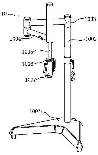
[0036] The correspondence between part names and serial numbers is as follows

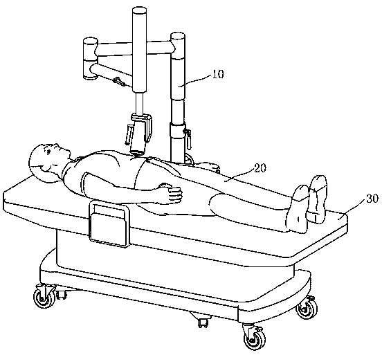
[0037] 10: Magnetic control equipment for the booster arm.

[0038] 1001: Removable base.

[0039] 1002: column.

[0040] 1003: the first horizontal active axis.

[0041] 1004: the second horizontal active axis.

[0042] 1005: lifting shaft.

[0043] 1006: Composite rotation axis.

[0044] 1007: Outer anchor magnet.

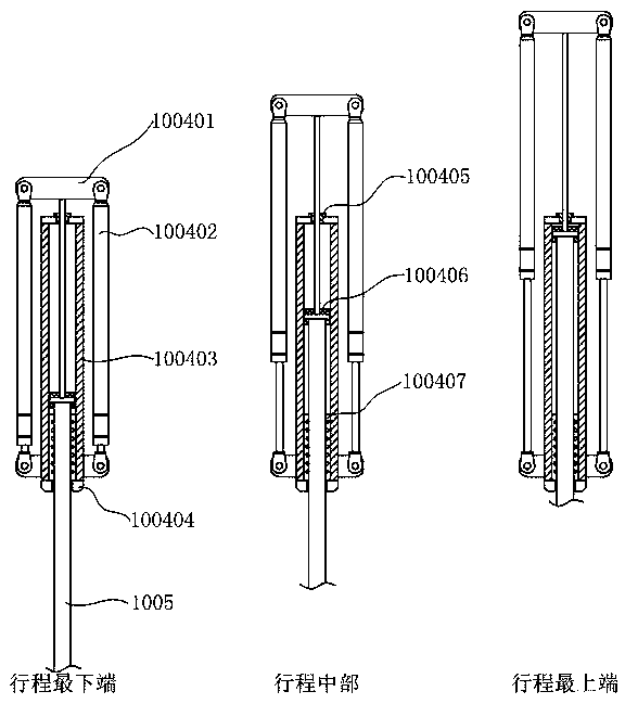
[0045] 100401: Balance bracket.

[0046] 100402: Elastic part.

[0047] 100403: Fixed sleeve.

[0048] 100404: Damping adjustment block.

[0049] 100405: Bushing.

[0050] 100406: connecting rod and buffer pad.

[0051] 100407: Linear bearing.

[0052] In order to make the technical problems, technical solutions and beneficial effects to be solved by the present invention clearer, the present invention will be further described in detail below in conjunction with the accompanying drawings and embodiments. It should be understood that the specific embodiments described her...


PUM


Abstract

The invention discloses magnetic control equipment with a booster arm. The equipment includes a movable base, a stand column, a first horizontal movable shaft, a second horizontal movable shaft, a lifting shaft, a composite rotating shaft and an outer anchor magnet; and the outer anchor magnet is fixed on the booster arm, the outer anchor magnet can move arbitrarily in a certain space range and rotate arbitrarily around two mutually perpendicular axes, a gravity balance component is arranged in the vertical direction to balance the gravity of the magnet, and each joint is provided with a damper to realize hovering of the magnet at any position and any posture. The magnetic control equipment with the booster arm provided by the invention reduces the number of personnel for endoscopic surgery, reduces space occupied by the surgery, enhances stability of magnet positioning while maintaining flexibility of magnet attitude adjustment, is convenient to operate and flexible to control, and improves the efficiency and success rate of the surgery.

Description

technical field [0001] The invention relates to the field of medical instruments, in particular to a magnetic control device that can be used for minimally invasive surgery. Background technique [0002] At present, in the medical field, endoscopic surgery has been affirmed and welcomed by more and more patients for its advantages of less trauma, less pain, and faster recovery. With the rapid development of medical technology, endoscopic surgery has been greatly popularized. The quality requirements of endoscopic surgery are also constantly improving. The current minimally invasive surgery usually requires 3 or more incisions on the chest / abdominal wall, including some poking holes that are only used as auxiliary functions for traction and exposure of the lesion. For patients, one more incision means more pain, and, for surgeons, the unavoidable "chopstick effect" in single-port endoscopic surgery greatly increases the difficulty of the operation, and it is difficult for the...

Claims


Application Information

Patent Timeline
IPC IPC(8): A61B90/50
CPCA61B90/50A61B2090/508
Inventor 张伟文彭国会宁浩董宜发
Owner SHENZHEN JIFU MEDICAL TECH CO LTD
Learn More