
Ultrasonic cleaning device for wafer cleaning

An ultrasonic cleaning and wafer technology, applied in the direction of using liquid cleaning methods, cleaning methods and utensils, chemical instruments and methods, etc., can solve the problems of central position damage, insufficient cleaning strength, damaged wafers, etc., to ensure the sameness , Easy to identify, even cleaning effect

Active Publication Date: 2020-04-10
爱阔特(上海)清洗设备制造有限公司
View PDF7 Cites 3 Cited by
  • Summary
  • Abstract
  • Description
  • Claims
  • Application Information

AI Technical Summary

Problems solved by technology

[0003] On the one hand, due to the different radii, the velocities of points on different circles on the wafer are different, and the closer to the center, the slower the velocity. On the contrary, the closer to the center, the stronger the received acoustic wave energy density, resulting in The cleaning intensity at the edge is not enough to meet the actual needs, while the center is damaged due to too much energy. On the other hand, this cleaning method is equivalent to drawing multiple spirals on the wafer surface until the wafer surface is completely covered. In fact, some points on the wafer may be scanned many times, and some shops do not even receive the acoustic energy, which increases cleaning unevenness and increases cleaning time
[0004] Secondly, silicon wafers are usually cleaned in a closed chamber and immersed in the cleaning solution, which makes it difficult to observe the rotation state of the wafer. When the wafer rotation is abnormal, the ultrasonic energy may damage the wafer.

Method used


Image

  • Ultrasonic cleaning device for wafer cleaning
  • Ultrasonic cleaning device for wafer cleaning
  • Ultrasonic cleaning device for wafer cleaning

Examples


Embodiment Construction

[0021] The following will clearly and completely describe the technical solutions in the embodiments of the present invention with reference to the accompanying drawings in the embodiments of the present invention. Obviously, the described embodiments are only some, not all, embodiments of the present invention. Based on the embodiments of the present invention, all other embodiments obtained by persons of ordinary skill in the art without making creative efforts belong to the protection scope of the present invention.

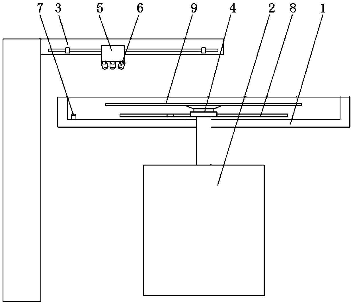
[0022] see Figure 1-4 , an ultrasonic cleaning device for wafer cleaning, comprising a cleaning chamber 1, a driving structure 2, and a moving arm 3, the output end of the driving structure 2 runs through the cleaning chamber 1 and is fixedly connected to the rotating arm 8, and the rotating arm 8 is eccentrically provided with The mobile table 4, when cleaning, the mobile table 4 fixes the wafer 9 through the suction cup, and when the rotating arm 8 rotates,...


PUM


Abstract

The invention relates to the technical field of integrated circuits, and discloses an ultrasonic cleaning device for wafer cleaning. The ultrasonic cleaning device includes a cleaning cavity, a driving structure and a moving arm, and the output end of the driving structure penetrates through the cleaning cavity and is fixedly connected to the rotating arm. According to the ultrasonic cleaning device for wafer cleaning, the moving speed of a servo structure gradually increases along with decrease of the distance between the servo structure and the center of a moving table, the decrease in the linear velocity of points near the center position is counteracted, and therefore ultrasonic energy received by each point remains uniform; meanwhile, the ultrasonic area of the device is linear, the movement speed of the servo structure and the rotation speed of the moving table are matched, the surface of an entire wafer can be completely cleaned at a time, due to eccentric rotation of the wafer,the rotation state of the wafer can be calculated through the time wasted by passing of a gap of the wafer through a position sensor; and meanwhile, the position of the wafer can be easily identified, so that the cleaning path can be the same every time to ensure the uniformity of cleaning, and the starting position and the cleaning path can be flexibly designed.

Description

technical field [0001] The invention relates to the technical field of integrated circuits, in particular to an ultrasonic cleaning device for wafer cleaning. Background technique [0002] With the improvement of single-wafer technology, the requirements for cleaning technology are getting higher and higher. Single-wafer cleaning technology is favored by many wafer foundries and large-scale integrated circuit manufacturers. Please refer to Figure 5 , while the wafer rotates at a constant speed, the ultrasonic generator sweeps back and forth from the edge to the center of the wafer until the entire wafer surface is cleaned. [0003] On the one hand, due to the different radii, the velocities of points on different circles on the wafer are different, and the closer to the center, the slower the velocity. On the contrary, the closer to the center, the stronger the received acoustic wave energy density, resulting in The cleaning intensity at the edge is not enough to meet the a...

Claims


Application Information

Patent Timeline
IPC IPC(8): B08B3/02
CPCB08B3/022B08B3/024B08B2203/0288B08B2203/02
Inventor 谢广钦
Owner 爱阔特(上海)清洗设备制造有限公司
Features
  • Generate Ideas
  • Intellectual Property
  • Life Sciences
  • Materials
  • Tech Scout
  • Unparalleled Data Quality
  • Higher Quality Content
  • 60% Fewer Hallucinations
Learn More