
A welding operation method for transition layer and cladding layer of clad steel plate

A technology of composite steel plate and operation method, applied in welding equipment, welding/welding/cutting items, arc welding equipment, etc., can solve the problems of increasing the difficulty of welding construction operations, waste of corrosion-resistant alloy materials, and increasing welding workload, etc. The effect of reducing the difficulty of welding operations, reducing secondary repairs, and improving the employment rate

Active Publication Date: 2021-05-04
中国石油天然气第一建设有限公司
View PDF6 Cites 0 Cited by
  • Summary
  • Abstract
  • Description
  • Claims
  • Application Information

AI Technical Summary

Problems solved by technology

[0002] With the upgrading of oil refining and chemical equipment, the demand for materials such as high corrosion resistance, low temperature resistance, high alloy stainless steel products and nickel-based alloys continues to increase. At the same time, if a large number of high corrosion resistance alloys are used, production costs will increase and corrosion resistance The waste of alloy materials, the traditional single material has been difficult to meet the needs of the development of refining and chemical equipment
On the basis of satisfying the service performance, the bimetal clad steel greatly reduces the manufacturing cost, and has obvious advantages in both performance and cost. It is more and more widely used in petrochemical equipment, but at the same time it also increases the difficulty of welding construction.
[0003] The groove type of cladding peeling is beneficial to control the composition of the transition layer and cladding layer, and ensure the corrosion resistance of the side in contact with the corrosive medium, but increases the welding workload

Method used


Image

  • A welding operation method for transition layer and cladding layer of clad steel plate
  • A welding operation method for transition layer and cladding layer of clad steel plate

Examples


Embodiment 1

[0038] The material of an engineering equipment in the company is 15CrMoR+0Cr13 composite steel plate, the thickness is (16+3) mm; the nickel-based electrode Ni337 is used, the diameter is ¢3.2, and it is welded by the traditional method. Due to the difficulty in the operation of the electrode and the difficulty in controlling the shape of the weld, there has been a Transition layer crack defect.

[0039] Adopt technical scheme of the present invention, step is as follows:

[0040] (1) Groove type: adopt V-shaped groove on the base side, and the peeling width of each side of the compound layer is 15mm;

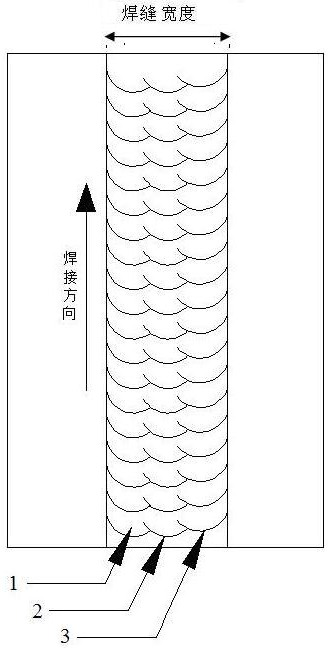
[0041](2) The transition layer is welded by the segmented horizontal welding operation method: the width of the stripped weld is 33mm;

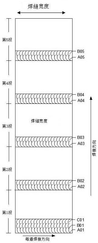
[0042] (3) Divide the weld seam into several sections with a length of about 180mm, start welding one piece at the lower part of the first section using the horizontal welding operation method, and start welding one piece at the lower part o...


PUM

PropertyMeasurementUnit
lengthaaaaaaaaaa
thicknessaaaaaaaaaa

Abstract

The invention introduces a welding operation method for the transition layer and the cladding layer of the composite steel plate, which is used for the vertical welding seam of the cylinder and the upward slope welding seam of the spherical head. The peeling width is not less than 12mm; the transition layer is welded by segmented horizontal welding, the peeling weld width is more than 25mm, and it is welded horizontally from one side of the groove to the other side; the weld is divided into small sections of 150‑200mm, and the first section is welded horizontally One, after stopping the arc, start welding at the lower part of the second section, a total of 4 to 6 sections of continuous welding; then carry out the second round of circulation until the welding is completed; divide the next section of welding seam into several sections of 150-200mm, Enter the next cycle until the transition layer is welded; cover welding repeats the above process until the welding is completed. The invention reduces the welding difficulty, improves the employment rate, the construction efficiency and the qualification rate of the welding film, reduces the waste of the length of the welding rod and the heat input, the dilution rate of the alloy elements is low, the structure of the weld seam is uniform, and the performance is excellent.

Description

technical field [0001] The invention relates to the field of welding operation technology, in particular to a welding operation method for a transition layer and a cladding layer of a composite steel plate. Background technique [0002] With the upgrading of oil refining and chemical equipment, the demand for materials such as high corrosion resistance, low temperature resistance, high alloy stainless steel products and nickel-based alloys continues to increase. At the same time, if a large number of high corrosion resistance alloys are used, production costs will increase and corrosion resistance The waste of alloy materials, the traditional single material has been difficult to meet the needs of the development of refining and chemical equipment. On the basis of satisfying the service performance, the bimetal clad steel has greatly reduced the manufacturing cost, and has obvious advantages in both performance and cost. It has been more and more widely used in petrochemical...

Claims


Application Information

Patent Timeline
Patent Type & Authority Patents(China)
IPC IPC(8): B23K9/025
CPCB23K9/025B23K2101/18B23K2103/04
Inventor 曹遂军丁自力裴先峰刘新海慕香奎王俊峰赵卫宁李军聂敏田波清蒋国辉黄琨周亚非黄珂珂薛正才周超刘申民
Owner 中国石油天然气第一建设有限公司
Learn More