
Fixing clamping device for laser engraving machine

A laser engraving machine and fixed clamping technology, applied in the field of laser engraving machines, can solve the problems of affecting the accuracy of engraving, inconvenient workpiece clamping, affecting the engraving quality, etc., and achieve the effect of convenient engraving and operation.

Inactive Publication Date: 2020-04-10
芜湖镭科智能科技股份有限公司
View PDF10 Cites 3 Cited by
  • Summary
  • Abstract
  • Description
  • Claims
  • Application Information

AI Technical Summary

Problems solved by technology

[0005] The object of the present invention is to provide a fixed clamping device for a laser engraving machine. By setting a workbench inside the frame, a clamping box is set on the top of the workbench, and an adjustment box is set on the bottom of the workbench. The workpiece is clamped and fixed, and the height can be easily adjusted to solve the inconvenience of clamping the workpiece proposed in the above-mentioned background technology. Unstable clamping will directly affect the accuracy of engraving and affect the quality of engraving, and the existing The problem that the clamping device is not convenient for adjusting the height of the workpiece

Method used


Image

  • Fixing clamping device for laser engraving machine
  • Fixing clamping device for laser engraving machine
  • Fixing clamping device for laser engraving machine

Examples


Embodiment Construction

[0027] The technical solutions in the embodiments of the present invention will be clearly and completely described below. Obviously, the described embodiments are only some of the embodiments of the present invention, but not all of them. The specific embodiments described here are only used to explain the present invention, not to limit the present invention. Based on the embodiments of the present invention, all other embodiments obtained by persons of ordinary skill in the art without making creative efforts belong to the protection scope of the present invention.

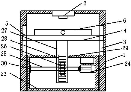
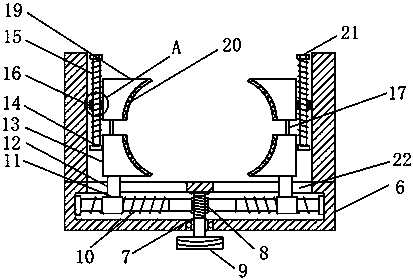
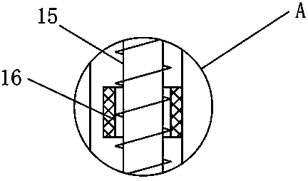
[0028] The present invention provides such Figure 1-6 The shown fixed clamping device for a laser engraving machine includes a frame 1, a clamping box 6 and an adjustment box 23. A laser engraving head 2, a workbench 4 and a clamping box 6 are arranged in the frame 1, and the laser engraving The head 2 is fixedly connected to the upper part of the frame 1, the workbench 4 is horizontally arranged and slidably...


PUM


Abstract

The invention discloses a fixing clamping device for a laser engraving machine. The fixing clamping device includes a machine frame, a clamping box and an adjustment box, a laser engraving head is fixedly connected to the upper part of the machine frame, a worktable is horizontally arranged and slidably installed in the machine frame, the clamping box is fixedly connected to the upper part of theworktable, a worm is rotatably installed inside the clamping box, a first threaded sleeve is fixedly connected to one end of a sliding rod, and one side of a second threaded sleeve is fixedly connected to a second clamping block; and one end of a rotating shaft of a motor is fixedly connected to a rotating rod, one side of a gear is in meshing connection with a rack, and the rack is fixedly connected to one side of a supporting column, and the upper part of the supporting column is fixedly connected to the bottom of the worktable. By arranging the worktable inside the machine frame, arrangingthe clamping box on the upper part of the worktable and arranging the adjustment box at the bottom of the worktable, a workpiece to be engraved can be clamped and fixed, and the height adjustment canbe conveniently carried out.

Description

technical field [0001] The invention belongs to the technical field of laser engraving machines, and in particular relates to a fixed clamping device for laser engraving machines. Background technique [0002] Laser engraving machine, as the name suggests, is an advanced equipment that uses laser to engrave materials that need to be engraved. Laser engraving machine is different from mechanical engraving machine and other traditional manual engraving methods. Laser engraving machine uses laser heat to engrave materials. , The laser in the laser engraving machine is its core. Generally speaking, the laser engraving machine is used in a wider range, and the engraving precision is higher, and the engraving speed is faster. Because the laser engraving machine has so many advantages, so Now the application of laser engraving machine has gradually replaced the traditional engraving equipment and methods, becoming the main engraving equipment. [0003] However, in the prior art, w...

Claims


Application Information

Patent Timeline
IPC IPC(8): B23K26/70B23K26/362B23K37/04
CPCB23K26/362B23K37/0443B23K26/702
Inventor 朱先勇白蕾朱俊权
Owner 芜湖镭科智能科技股份有限公司
Learn More