
Vacuum dual film laminating machine

A technology of double laminating machine and laminating machine, which can be applied to other household appliances, etc., can solve the problems of low production efficiency and low production quantity, and achieve the effects of improving production efficiency, reducing production cost and increasing utilization rate

Pending Publication Date: 2020-04-10
佛山市南海区双志包装机械有限公司
View PDF0 Cites 0 Cited by
  • Summary
  • Abstract
  • Description
  • Claims
  • Application Information

AI Technical Summary

Problems solved by technology

However, due to the characteristics of water and oil absorption of unprocessed pulp products, it cannot be used directly in some cases, and it is necessary to coat some surfaces of the pulp products through a thermal coating process to make the parts With waterproof and oil-proof performance, the existing vacuum laminating machine only has one parking position for the transport mold, and the transport mold travels back and forth between the parking position and the vacuum chamber. The uncoated pulp embryos are placed on the uncoated pulp embryos, and then a coating cycle is started. In this coating cycle: the transport mold is pushed into the vacuum chamber---the pulp embryos are vacuum coated---the coated pulp The embryo returns to the parking position with the transport mold. It can be seen that the only transport mold is reciprocating during the production process, which belongs to a vacuum laminating machine with reciprocating feeding. However, such a machine has the disadvantage of low production efficiency, which is reflected in : In the process of workers taking off the coated pulp embryos and putting uncoated pulp embryos on, the vacuum chamber is actually in a waiting state, and in the process of vacuuming the film, the workers are in a waiting state, which is results in a lower production quantity per unit of time, so one would like to address this

Method used


Image

  • Vacuum dual film laminating machine
  • Vacuum dual film laminating machine
  • Vacuum dual film laminating machine

Examples


Embodiment Construction

[0015] In order to make the technical means, creative features, goals and effects achieved by the present invention easy to understand, the present invention will be further described below in conjunction with specific embodiments.

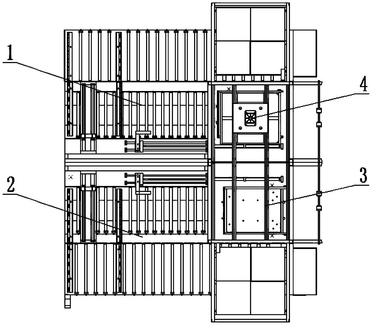
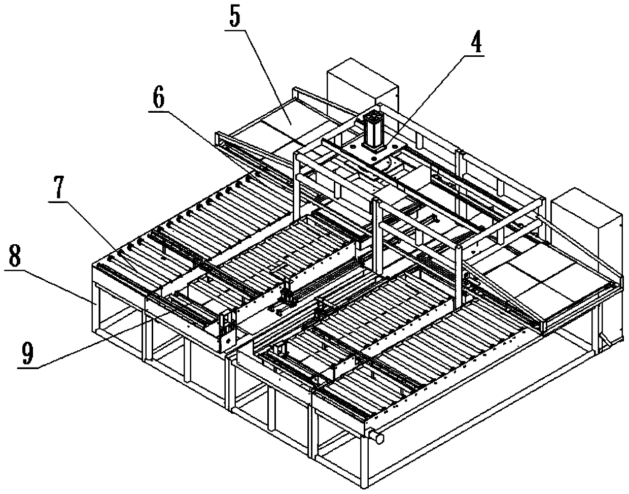
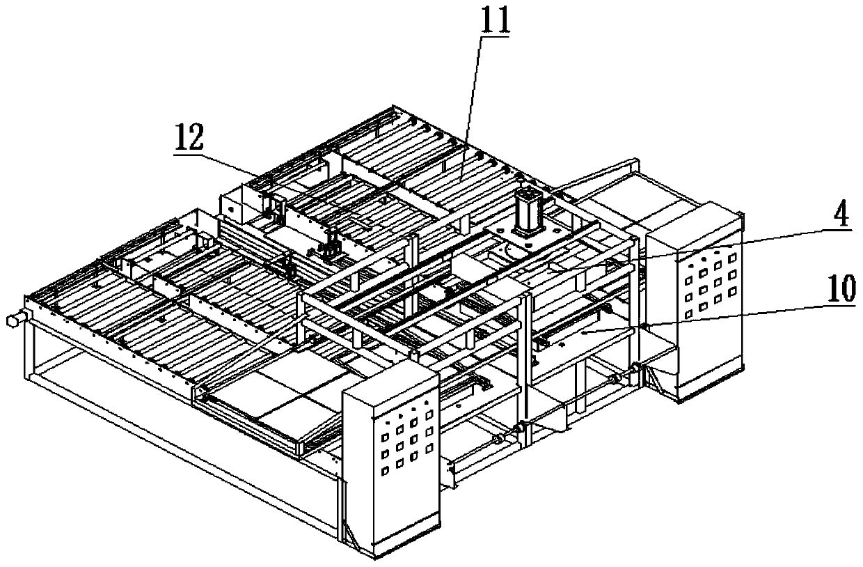
[0016] Such as Figure 1-3 As shown, a vacuum double laminating machine includes a frame 8 for installing various devices, a first laminating machine 1 and a second laminating machine 2 are arranged on the frame 1, the first laminating machine 1 and the The second laminating machine 2 is arranged symmetrically, and both the first laminating machine 1 and the second laminating machine 2 include a first roll set 12 and a second roll set 11, and the first roll set 12 and the second roll set 11 A transport mold 5 is placed on it, one end of the first roller group 12 is set as the first parking position 9, the other end of the first roller group 12 is provided with a vacuum chamber 10, and one end of the second roller group 11 is set as the second park...


PUM


Abstract

The invention discloses a vacuum dual film laminating machine. The vacuum dual film laminating machine comprises a frame used for mounting various devices, wherein the frame is provided with a first film laminating machine and a second film laminating machine; each of the first film laminating machine and the second film laminating machine comprises a first roller set and a second roller set; a heating box sliding rail is arranged above two groups of vacuum chambers of the first roller set and the second roller set; one set of heating boxes are arranged on the heating box sliding rail. According to the vacuum dual film laminating machine, when the first film laminating machine is used for carrying out a film laminating process, the second film laminating machine is used for conveying transportation molds; when the film laminating process of the first film laminating machine is ended, the transportation molds are conveyed; the heating boxes are moved to the second film laminating machine through the heating box sliding rail for carrying out the film laminating process; the utilization rate of the heating boxes is increased; the vacuum chambers and workers maintain working states with relatively full load; the production efficiency is greatly improved; compared with a single film laminating machine, the vacuum dual film laminating machine is more energy-saving; one set of heatingboxes are applied to two sets of film laminating machines; and the production cost of the enterprise can be reduced.

Description

technical field [0001] The invention relates to the field of laminating machine production, in particular to a vacuum double laminating machine. Background technique [0002] In order to reduce environmental pollution, more and more existing packaging materials and catering containers are made of pulp as a raw material through molding. Such pulp products can be packaging boxes for mobile phones or disposable lunch boxes. However, due to the characteristics of water and oil absorption of unprocessed pulp products, it cannot be used directly in some cases, and it is necessary to coat some surfaces of the pulp products through a thermal coating process to make the parts With waterproof and oil-proof performance, the existing vacuum laminating machine only has one parking position for the transport mold, and the transport mold travels back and forth between the parking position and the vacuum chamber. The uncoated pulp embryos are placed on the uncoated pulp embryos, and then ...

Claims


Application Information

Patent Timeline
IPC IPC(8): B29C65/02B29L9/00
CPCB29C65/02B29C66/45B29L2009/00
Inventor 范至交
Owner 佛山市南海区双志包装机械有限公司
Features
  • Generate Ideas
  • Intellectual Property
  • Life Sciences
  • Materials
  • Tech Scout
  • Unparalleled Data Quality
  • Higher Quality Content
  • 60% Fewer Hallucinations
Learn More