Briquetting device for scrap metal recycling

A technology of scrap metal and block components, applied in the direction of presses, manufacturing tools, etc., can solve the problems of not equipped with automatic blanking, affecting the efficiency of briquetting, complex structure, etc.

Active Publication Date: 2020-04-10
广西千吉科技有限公司
View PDF8 Cites 5 Cited by
  • Summary
  • Abstract
  • Description
  • Claims
  • Application Information

AI Technical Summary

Problems solved by technology

[0002] The waste generated in life, the used (eliminated) waste molds in production activities, the steel bars produced in the dismantling of old buildings, and the waste metals such as scrapped cars, waste gas tanks and metal cans produced in the consumption process are sorted, collected, and regenerated. Smelting and manufacturing various steel products can save resources and energy used in the steelmaking process, and finally achieve the purpose of protecting the environment. For this reason, scrap metals of various shapes and materials need to be classified first, and then classified according to the material They are classified, processed and shaped into scrap metal briquettes of various sizes and shapes, so that the steelmaking plant can be directly put into the furnace for use. The existing scrap metal briquetting equipment has a complex structure and is not equipped with automatic feeding, requiring manual labor. Carrying out operation and blanking will affect the efficiency of briquetting. Therefore, we propose a briquetting device for scrap metal recycling in order to solve the above-mentioned problems

Method used


Image

  • Briquetting device for scrap metal recycling
  • Briquetting device for scrap metal recycling
  • Briquetting device for scrap metal recycling

Examples


Embodiment Construction

[0027] A number of embodiments of the present invention will be disclosed in the following figures. For the sake of clarity, many practical details will be described together in the following description. It should be understood, however, that these practical details should not be used to limit the invention. That is, in some embodiments of the invention, these practical details are not necessary. In addition, for the sake of simplifying the drawings, some well-known and commonly used structures and components will be shown in a simple schematic manner in the drawings.

[0028] In addition, in the present invention, descriptions such as "first", "second" and so on are used for description purposes only, and do not refer to the meaning of order or sequence, nor are they used to limit the present invention, but are only for the purpose of distinguishing the following The components or operations described by the same technical terms are only used, but should not be understood a...


PUM


Abstract

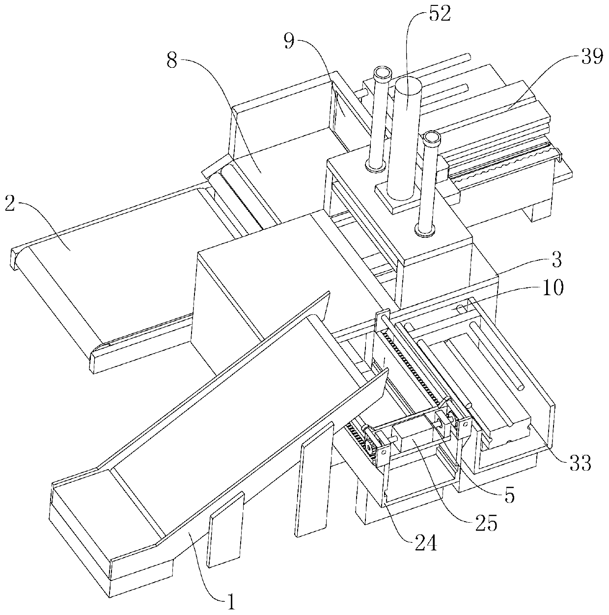
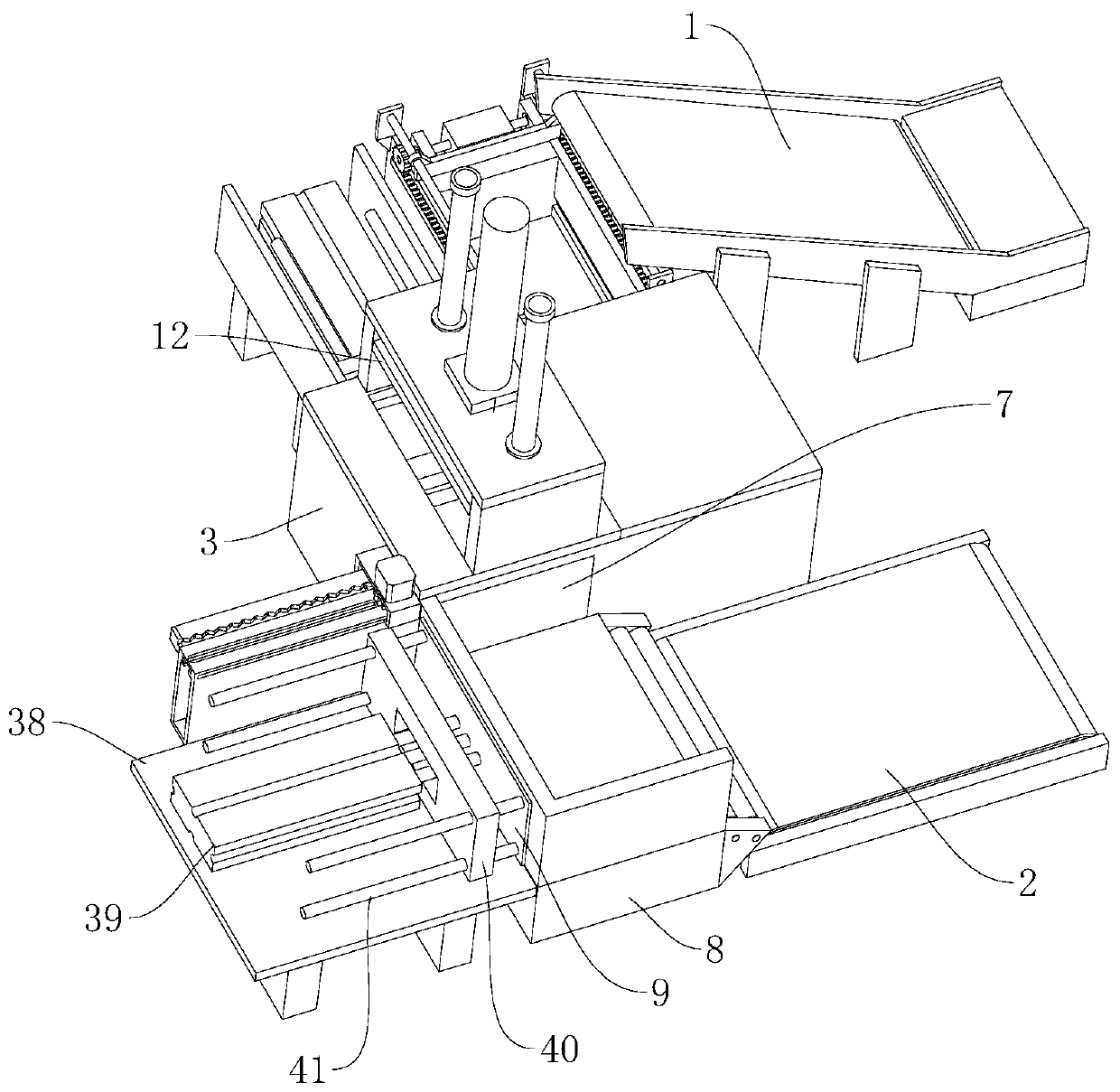
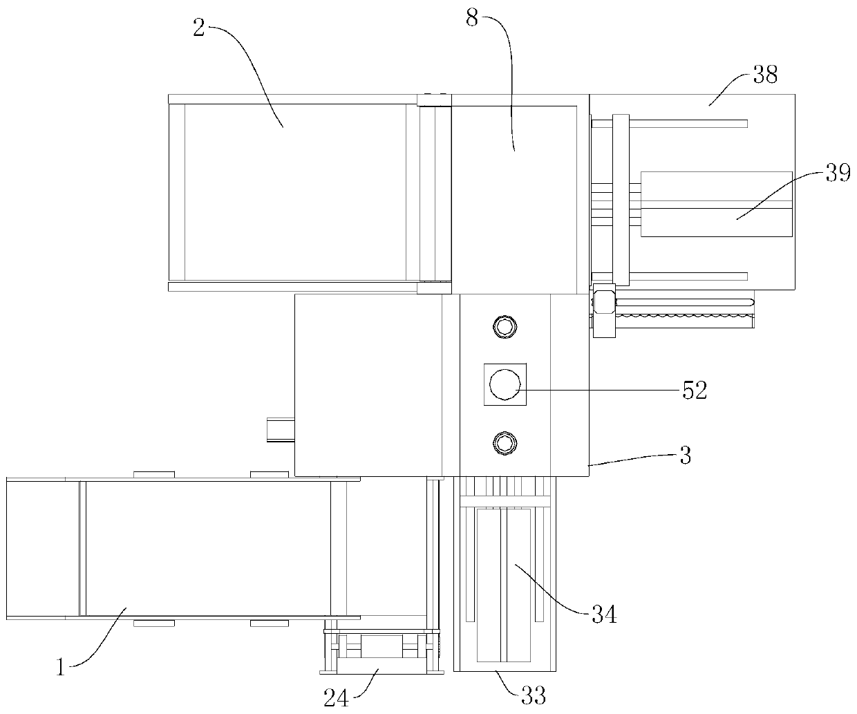
The invention relates to the field of scrap metal recycling, in particular to a briquetting device for scrap metal recycling. The briquetting device includes a feeding conveyor and a discharge conveyor, and further includes a processing bin, a material moving assembly and a briquetting assembly, wherein the material moving assembly and the briquetting assembly are installed on the processing bin.A feed inlet is formed in the side, located at the feeding conveyor, of the processing bin, and a feeding assembly is arranged on the side, located at the feed inlet, of the processing bin. The feeding assembly is provided with a feeding push plate which can move to the feed inlet, and a discharge port is formed in the side, close to the discharge conveyor, of the processing bin. A plate moving assembly is arranged on one side of the discharge port, and the plate moving assembly is provided with a discharge baffle. A material moving track is arranged on one side of the discharge baffle, and amaterial moving push plate is arranged on the material moving track. A discharge push plate is arranged on the end, away from the discharge port, of the processing bin, and a moving bottom frame is arranged at the working end of the material moving assembly. The briquetting assembly is provided with a hydraulic plate capable of extending into the processing bin. The briquetting device is simple tooperate, scrap metal only needs to be fed in sequence, and automatic briquetting and discharge can be performed, so that the briquetting efficiency is improved.

Description

technical field [0001] The invention relates to the field of scrap metal recycling, in particular to a briquetting device for scrap metal recycling. Background technique [0002] The waste generated in life, the used (eliminated) waste molds in production activities, the steel bars produced in the dismantling of old buildings, and the waste metals such as scrapped cars, waste gas tanks and metal cans produced in the consumption process are sorted, collected, and regenerated. Smelting and manufacturing various steel products can save resources and energy used in the steelmaking process, and finally achieve the purpose of protecting the environment. For this reason, scrap metals of various shapes and materials need to be classified first, and then classified according to the material They are classified, processed and shaped into scrap metal briquettes of various sizes and shapes, so that the steelmaking plant can be directly put into the furnace for use. The existing scrap me...

Claims


Application Information

Patent Timeline
Patent Type & Authority Applications(China)
IPC IPC(8): B30B9/32B30B15/30B30B15/32
CPCB30B9/327B30B15/30B30B15/32
Inventor 金晨
Owner 广西千吉科技有限公司
Why Eureka
Try Eureka