Passenger car passenger armrest bracket mounting structure and mounting method thereof

A technology of armrest bracket and installation structure, which is applied to vehicle components, transportation and packaging, and special positions of vehicles, etc. It can solve problems such as difficult molding, complex structure of three-claw passenger armrest bracket, and failure of passenger armrests, so as to reduce passenger armrests. Failure problems, easy control of production quality, and simple shape effects

Inactive Publication Date: 2020-04-10
江苏开沃汽车有限公司
View PDF5 Cites 1 Cited by
  • Summary
  • Abstract
  • Description
  • Claims
  • Application Information

AI Technical Summary

Problems solved by technology

[0002] At present, there are two structures for the installation structure of the passenger armrest bracket commonly used in passenger cars, one of which is the three-claw type ( figure 1 ); the other is Z-shaped ( figure 2 ); Among them, the structure of the three-claw type passenger armrest bracket is more complicated, and it is more difficult to form. If the cross-sectional size of the upper side beam is small, it will have a great impact on the wiring harness arrangement
The shape of the Z-shaped passenger armrest bracket is relatively simple and the layout is good, but its rigidity is poor, and it is easy to cause the passenger armrest to fail due to the deformation of the passenger armrest bracket during daily use.
Moreover, if the distance between the passenger handrail and the side beam is too far during the design process, it will make it difficult to meet the rigidity requirements of the three-claw and Z-shaped passenger handrail brackets

Method used


Image

  • Passenger car passenger armrest bracket mounting structure and mounting method thereof
  • Passenger car passenger armrest bracket mounting structure and mounting method thereof
  • Passenger car passenger armrest bracket mounting structure and mounting method thereof

Examples


Embodiment Construction

[0019] The present invention will be further described below in conjunction with the accompanying drawings.

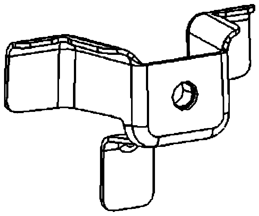
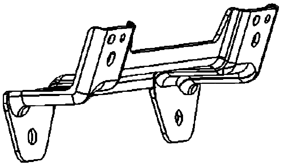
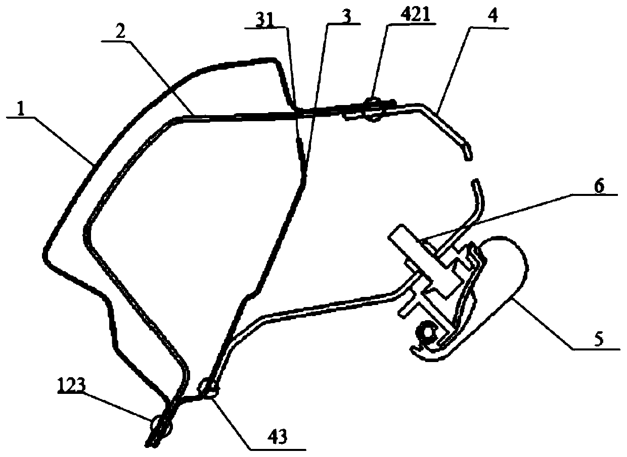
[0020] The installation structure of the passenger armrest bracket of the passenger car of the present invention comprises a side wall outer panel 1, a side wall edge beam reinforcement plate 2, a side wall inner panel 3, a passenger armrest bracket 4 and a passenger handrail 5, a side wall outer panel 1, a side wall edge beam The lower part of the reinforcing plate 2 and the side wall inner panel 3 is welded together by the first welding spot 123, and the position where the upper part of the side wall inner panel 3 is welded with the side wall outer panel 1 and the side wall side sill reinforcement plate 2 forms a gap 31, and the gap 31 The purpose is to prevent the occurrence of four-layer welding during the welding process, which may lead to bad solder joints. The passenger armrest bracket 4 is welded together with the side wall side sill reinforcement plate 2 and t...


PUM


Abstract

The invention discloses a passenger car passenger armrest support mounting structure and a mounting method thereof. The mounting structure comprises a side wall outer plate, a side wall edge beam reinforcing plate, a side wall inner plate, a passenger armrest support and a passenger armrest. The lower parts of the side wall outer plate, the side wall edge beam reinforcing plate and the side wall inner plate are welded together through a first welding spot. The passenger armrest support, the side wall edge beam reinforcing plate and the side wall outer plate are welded together through a secondwelding spot. The passenger armrest support and the side wall inner plate are welded together through a third welding spot. The passenger armrest is fixedly connected to the passenger armrest supportthrough bolts. The passenger armrest support mounting structure is simple in structure, good in rigidity and capable of improving the rigidity of passenger armrest support mounting points on a largescale.

Description

Technical field: [0001] The invention relates to an installation structure of a passenger armrest bracket of a passenger car and an installation method thereof, belonging to the technical field of passenger cars. Background technique: [0002] At present, there are two structures for the installation structure of the passenger armrest bracket commonly used in passenger cars, one of which is the three-claw type ( figure 1 ); the other is Z-shaped ( figure 2 ); Among them, the structure of the three-claw type passenger armrest bracket is more complicated, and it is more difficult to form. If the cross-sectional size of the upper side beam is small, it will have a greater impact on the wiring harness arrangement. The shape of the Z-shaped passenger armrest bracket is relatively simple and the arrangement is good, but its rigidity is poor, and it is easy to cause the passenger armrest to fail due to the deformation of the passenger armrest bracket during daily use. In additio...

Claims


Application Information

Patent Timeline
Patent Type & Authority Applications(China)
IPC IPC(8): B60N3/02
CPCB60N3/026
Inventor 王超巫振环郭丽许冰程红宋荣会蒋建忠赵超张晓龙何永攀吴龙八
Owner 江苏开沃汽车有限公司
Why Eureka
Try Eureka