Cutting device for package printing and using method thereof

A cutting device, packaging and printing technology, applied in the direction of transportation and packaging, sending objects, thin material processing, etc., can solve the problems affecting the cutting quality, limited scope of application, and affecting the accuracy of cardboard conveying, so as to ensure the quality of cutting and the scope of application wide effect

Inactive Publication Date: 2020-04-10
重庆市永川区华泰印务有限公司
View PDF5 Cites 8 Cited by
  • Summary
  • Abstract
  • Description
  • Claims
  • Application Information

AI Technical Summary

Problems solved by technology

[0003] The purpose of the present invention is to provide a cutting device for packaging and printing in order to solve the above problems, to solve the problem that the position of the cutting bottom plate of the current cutting device in the prior art is fixed, and there is friction between the cutting bottom plate and the cardboard when the cardboard is conveyed. , affecting the conveying accuracy of the cardboard, thereby affecting the cutting quality; at the same time, the positioning of different cutting lengths cannot be realized, and the scope of application is limited and other technical problems

Method used


Image

  • Cutting device for package printing and using method thereof
  • Cutting device for package printing and using method thereof
  • Cutting device for package printing and using method thereof

Examples


Embodiment Construction

[0030] In order to make the purpose, technical solution and advantages of the present invention clearer, the technical solution of the present invention will be described in detail below. Apparently, the described embodiments are only some of the embodiments of the present invention, but not all of them. Based on the embodiments of the present invention, all other implementations obtained by persons of ordinary skill in the art without making creative efforts fall within the protection scope of the present invention.

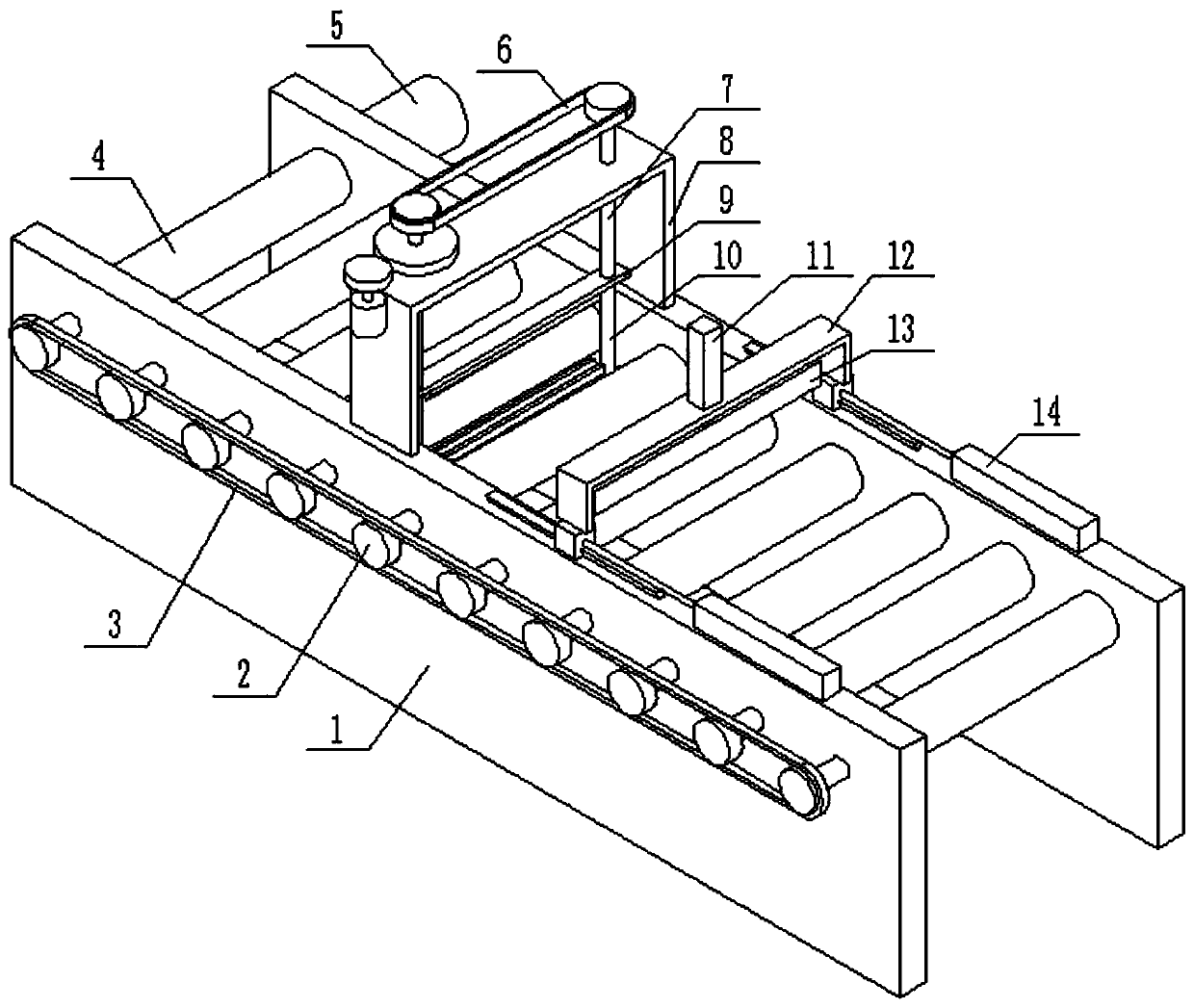
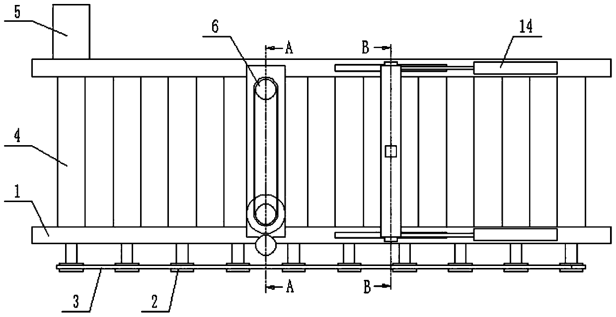
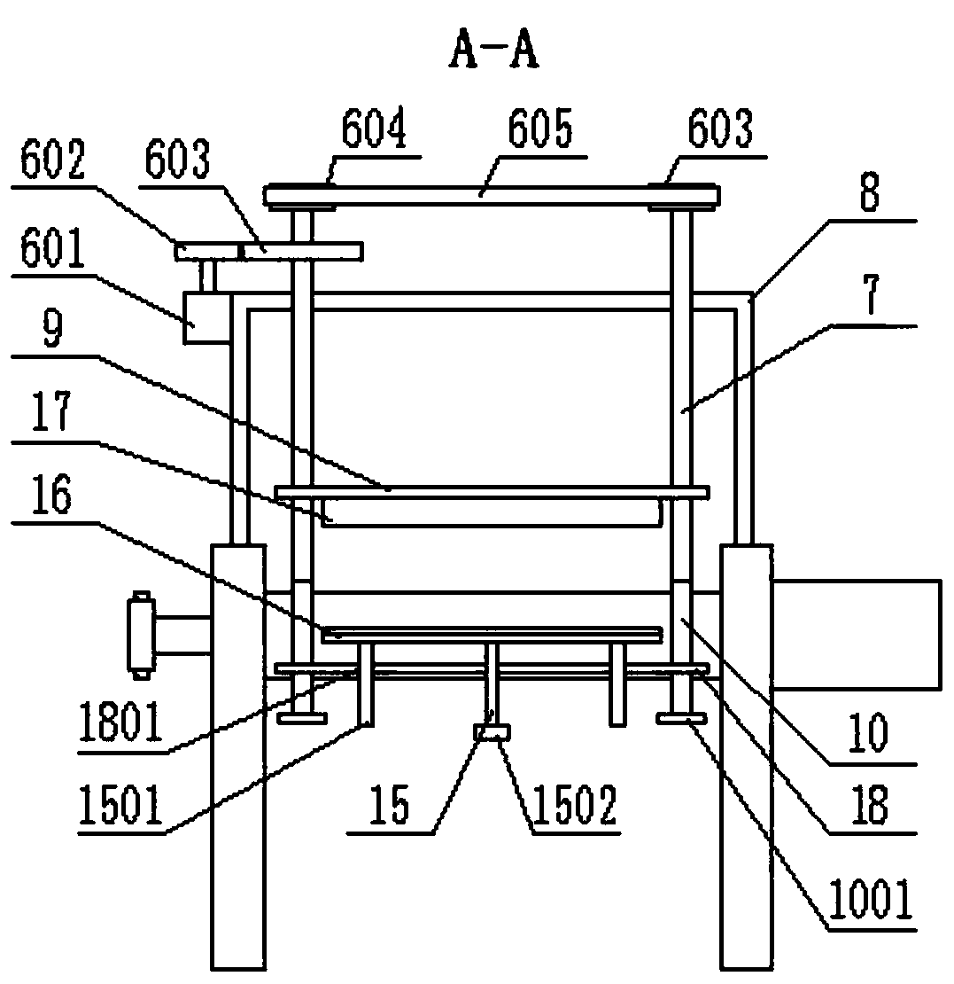
[0031] see Figure 1-Figure 4 As shown, the present invention provides a cutting device for packaging and printing, including a frame 1, a plurality of conveying rollers 4 are evenly installed inside the frame 1, and the ends of the conveying rollers 4 pass through the frame 1 and are equipped with sprockets 2 , all sprocket wheels 2 are connected with a chain 3 in transmission, and a conveying motor 5 is installed on the outside of the frame 1, and the conveyi...


PUM


Abstract

The invention discloses a cutting device for package printing and a using method thereof. The cutting device comprises a rack; a fixed frame and a sliding frame capable of moving on the upper surfaceon the rack are arranged on the upper surface of the rack; an electric positioning cylinder is mounted on the upper surface of the sliding frame; a positioning plate is connected with an output end ofthe electric positioning cylinder; a vertical first screw rod is rotationally mounted on the upper surface of the fixed frame; a second screw rod is coaxially connected with the bottom end of the first screw rod; a first lifting plate and a second lifting plate are separately mounted on the outer sides of the first screw rod and the second screw rod through threads; a cutting knife is connected to the bottom surface of the first lifting plate; and a cutting bottom plate is arranged on the upper surface of the second lifting plate. The cutting device has the benefits that the lifting of the cutting bottom plate can be realized, and the cutting bottom plate assists the cutting knife in cutting, so that the influence on paperboard transporting can be prevented, and the cutting quality is ensured; and the sliding frame is driven by a positioning driving piece to move to adjust the position of the positioning plate, so that the positioning requirements on different cutting lengths can be met, and the application range is wide.

Description

technical field [0001] The invention relates to the technical field of cutting devices, in particular to a cutting device for packaging and printing and a method for using the same. Background technique [0002] In the packaging and printing process of cardboard, it is necessary to use a cutting device to cut the cardboard. In order to ensure the cutting quality, a cutting bottom plate is provided under the cutting knife, and the cardboard is cut through the cutting bottom plate and the cutting knife. However, the position of the cutting bottom plate of the current cutting device is fixed, and there is friction between the cutting bottom plate and the cardboard when the cardboard is conveyed, which affects the conveying accuracy of the cardboard, thereby affecting the cutting quality; at the same time, it is impossible to realize the positioning of different cutting lengths. limited. Contents of the invention [0003] The purpose of the present invention is to provide a c...

Claims


Application Information

Patent Timeline
Patent Type & Authority Applications(China)
IPC IPC(8): B65H35/06
CPCB65H35/06B65H2701/176
Inventor 林贤满
Owner 重庆市永川区华泰印务有限公司
Why Eureka
Try Eureka