Supercharge Your Innovation With Domain-Expert AI Agents!

Vertical axis wind driven generator

A technology of wind generators and vertical shafts, which is applied to wind turbines, wind motor combinations, and wind turbines at right angles to the wind direction, etc. It can solve problems such as small wind receiving area, increased rotational resistance, and complex design and manufacture.

Inactive Publication Date: 2020-04-10
李燕芳
View PDF7 Cites 1 Cited by
  • Summary
  • Abstract
  • Description
  • Claims
  • Application Information

AI Technical Summary

Problems solved by technology

[0002] Small wind turbines can be divided into horizontal axis and vertical axis according to the direction of the rotation axis. Horizontal axis wind turbines have defects such as complicated design and manufacture and high cost, while vertical axis wind turbines are suitable for wind energy without conventional power grids. Families in remote rural areas, pastoral areas, mountainous areas and islands with relatively rich resources are also suitable for small units such as border posts, microwave stations, road stations, small railway stations, meteorological stations (stations), etc. In addition to the needs of entertainment and life, it can also supply power for navigation lights, microwave communications, TV turntables and other instruments and meters. For areas rich in wind resources, it is an ideal power supply equipment for families and small power. The existing vertical axis wind turbines Its wind-receiving area is small, if a windward structure is directly installed on the wind guide vane, it will increase the rotational resistance, thereby reducing the power generation efficiency

Method used


Image

  • Vertical axis wind driven generator
  • Vertical axis wind driven generator
  • Vertical axis wind driven generator

Examples


Embodiment Construction

[0022] The present invention will be described in further detail below in conjunction with the accompanying drawings and specific embodiments.

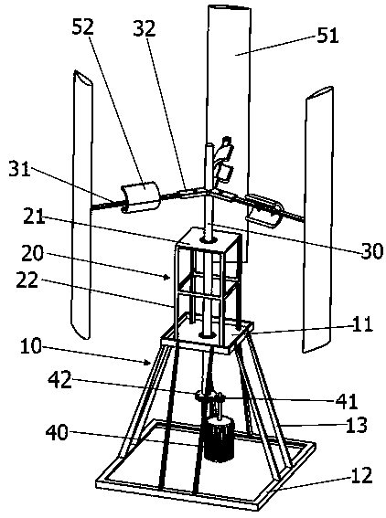
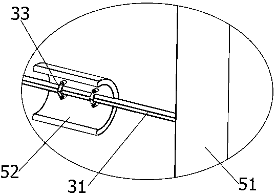
[0023] See Figure 1-3 As shown, in order to achieve the above purpose, the present invention provides a vertical axis wind power generator, which includes: a base 10 , a supporting platform 20 , a rotating shaft 30 , a wind guide unit and a generator 40 .

[0024] The base 10 includes a connecting plate 11 and a chassis 12, the connecting plate 11 is provided with a first through hole 111, the connecting plate 11 is located above the chassis 12, the connecting plate 11 and the chassis 12 are fixedly connected by a support rod 13, and the bottom The frame 12 and the connecting plate 11 realize the support of the vertical axis wind turbine 40 .

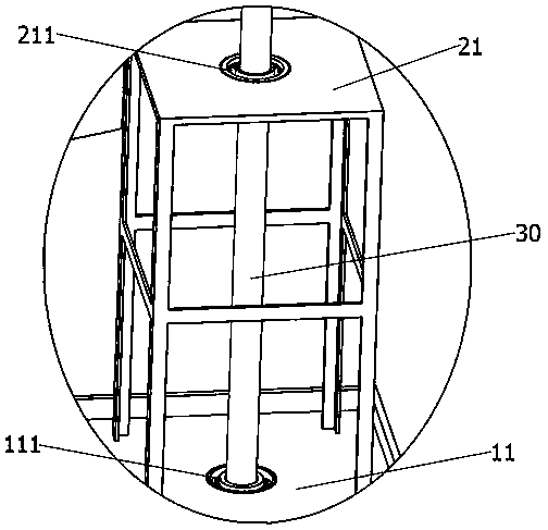
[0025] The support platform 20 is connected above the base 10, the support platform 20 includes a top plate 21 and legs 22 arranged on the top plate 21, the legs 22 are fixedly connected to t...


PUM


Abstract

The invention provides a vertical axis wind driven generator. The vertical axis wind driven generator comprises a base, a supporting table, a rotating shaft, an air guide unit and an electric generator. The base comprises a connecting plate and a bottom frame, a first through hole is formed in the connecting plate, the supporting table comprises a top plate and supporting legs, the supporting table is fixedly connected to the connecting plate, a second through hole is formed in the top plate, the rotating shaft is arranged in the first through hole and the second through hole in a penetratingmanner, the end part of the rotating shaft is connected with a transmission gear, an input shaft of the electric generator is provided with a connecting gear, the air guide unit comprises air guide blades and an arc air guide plate, the air guide blades are driven by wind to drive the rotating shaft to rotate, through a gear set, wind is transmitted to the electric generator to generate electric energy, and the arc air guide plate is located on a connecting rod. The windward area can be increased, when wind acts on the arc air guide plate, the rotating shaft can be pushed to rotate, the arc air guide plate can reduce the wind resistance during flowing of the airflow, and the power generation efficiency can be improved.

Description

technical field [0001] The invention relates to the technical field of wind power generation equipment, in particular to a vertical axis wind power generator. Background technique [0002] Small wind turbines can be divided into horizontal axis and vertical axis according to the direction of the rotation axis. Horizontal axis wind turbines have defects such as complicated design and manufacture and high cost, while vertical axis wind turbines are suitable for wind energy without conventional power grids. Families in remote rural areas, pastoral areas, mountainous areas and islands with relatively rich resources are also suitable for small units such as border posts, microwave stations, road stations, small railway stations, meteorological stations (stations), etc. In addition to the needs of entertainment and life, it can also supply power for navigation lights, microwave communications, TV turntables and other instruments and meters. For areas rich in wind resources, it is ...

Claims


Application Information

Patent Timeline
IPC IPC(8): F03D9/25F03D3/06
CPCF03D3/005F03D3/06F03D3/061F03D9/25Y02E10/74
Inventor 李燕芳
Owner 李燕芳
Features
  • R&D
  • Intellectual Property
  • Life Sciences
  • Materials
  • Tech Scout
  • Unparalleled Data Quality
  • Higher Quality Content
  • 60% Fewer Hallucinations
Learn More