Humidifier with oriented flow guide function

A technology for humidifiers and guide tubes, which is applied in air humidification systems, heating methods, household appliances, etc., can solve problems such as no specific solutions, and achieve the effect of ingenious structure, good market promotion prospects, and improved user experience

Inactive Publication Date: 2020-04-10
AUONE ELECTRONICS MFG
View PDF8 Cites 0 Cited by
  • Summary
  • Abstract
  • Description
  • Claims
  • Application Information

AI Technical Summary

Problems solved by technology

[0004] It can be seen that for humidifiers, there are still many practical problems that need to be dealt with urgently in practical applications (automatic adjustment of spray speed according to the distance between the human body and the humidifier, etc.) and many specific solutions have not been proposed.

Method used


Image

  • Humidifier with oriented flow guide function
  • Humidifier with oriented flow guide function
  • Humidifier with oriented flow guide function

Examples


Embodiment 1

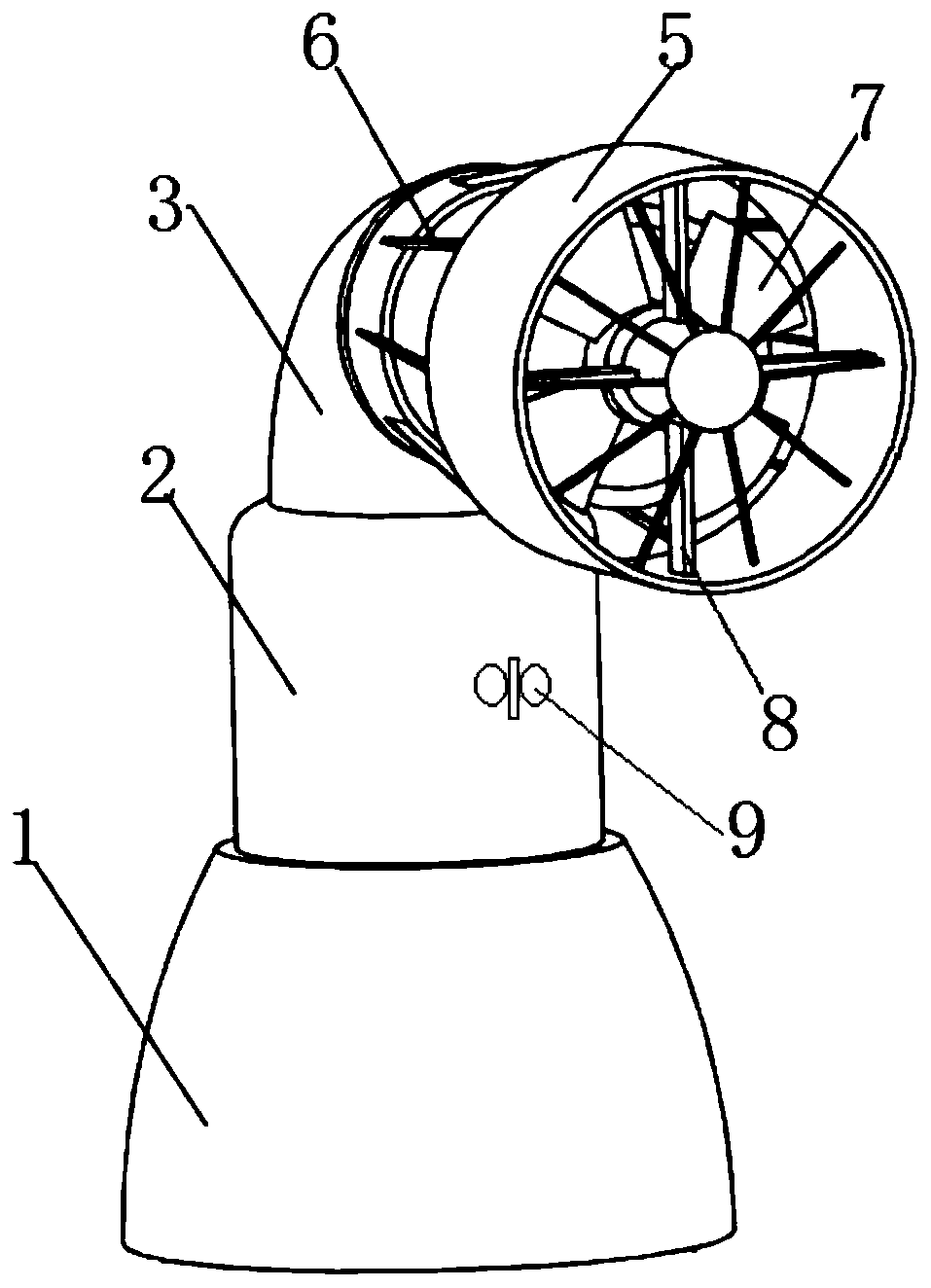
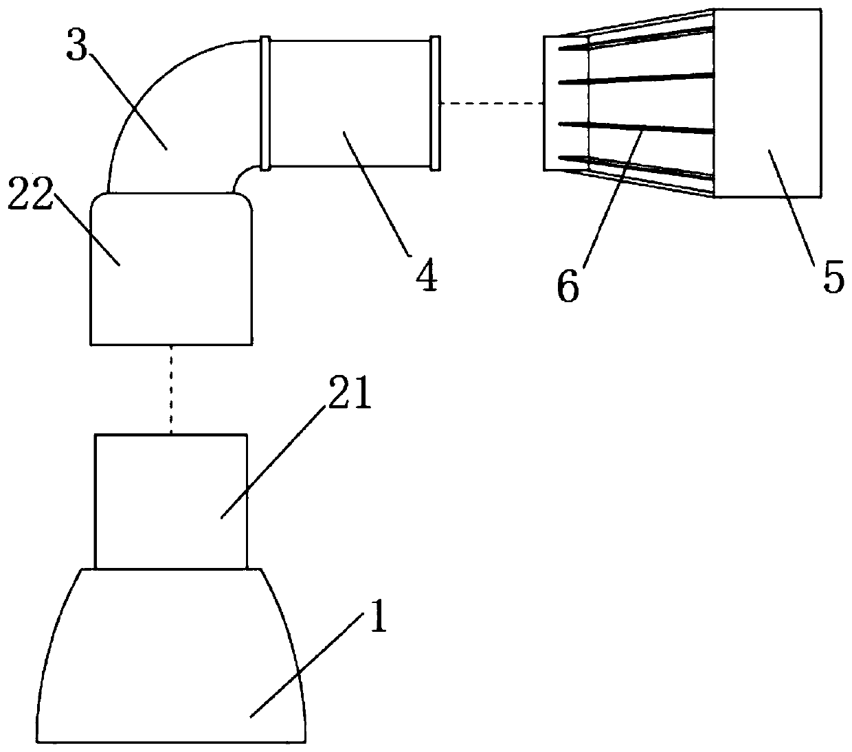
[0036] Such as figure 1 , figure 2 As shown, a humidifier with directional diversion includes a humidifier body 1, a mist outlet is provided on the humidifier body 1, and a guide tube is provided above the mist outlet, and the guide tube includes a horizontal part 4, bent part 3 and vertical part 2. The vertical part 2 includes a first connecting pipe 21 and a second connecting pipe 22 , one end of the first connecting pipe 21 is spirally connected to the mist outlet, and the other end of the first connecting pipe 21 is connected to the second connecting pipe 22 The other end of the second connecting pipe 22 communicates with one end of the bending part 3, the other end of the bending part 3 communicates with one end of the transverse part 4, and the inner wall of the other end of the transverse part 4 A blower fan 7 is provided in the middle. The humidifier includes an atomizing device and a water storage tank (not shown in the figure). The atomizing device can be an ultr...

Embodiment 2

[0044] Such as figure 1 , figure 2 As shown, a humidifier with directional diversion includes a humidifier body 1, a mist outlet is provided on the humidifier body 1, and a guide tube is provided above the mist outlet, and the guide tube includes a horizontal part 4, bent part 3 and vertical part 2. The vertical part 2 includes a first connecting pipe 21 and a second connecting pipe 22 , one end of the first connecting pipe 21 is spirally connected to the mist outlet, and the other end of the first connecting pipe 21 is connected to the second connecting pipe 22 The other end of the second connecting pipe 22 communicates with one end of the bending part 3, the other end of the bending part 3 communicates with one end of the transverse part 4, and the inner wall of the other end of the transverse part 4 A blower fan 7 is provided in the middle. The humidifier includes an atomizing device and a water storage tank (not shown in the figure). The atomizing device can be an ultr...

Embodiment 3

[0057] Such as figure 1 , figure 2 As shown, a humidifier with directional diversion includes a humidifier body 1, a mist outlet is provided on the humidifier body 1, and a guide tube is provided above the mist outlet, and the guide tube includes a horizontal part 4, bent part 3 and vertical part 2. The vertical part 2 includes a first connecting pipe 21 and a second connecting pipe 22 , one end of the first connecting pipe 21 is spirally connected to the mist outlet, and the other end of the first connecting pipe 21 is connected to the second connecting pipe 22 The other end of the second connecting pipe 22 communicates with one end of the bending part 3, the other end of the bending part 3 communicates with one end of the transverse part 4, and the inner wall of the other end of the transverse part 4 A blower fan 7 is provided in the middle. The humidifier includes an atomizing device and a water storage tank (not shown in the figure). The atomizing device can be an ultr...


PUM

PropertyMeasurementUnit
Resistanceaaaaaaaaaa

Abstract

The invention provides a humidifier with an oriented flow guide function. The humidifier comprises a humidifier body; a fog outlet is formed in the humidifier body; a guide pipe is arranged above thefog outlet, and comprises a horizontal part, a bent part and a longitudinal part; the longitudinal part comprises a first connecting pipe and a second connecting pipe; one end of the first connectingpipe is connected with the fog outlet spirally, and the other end of the first connecting pipe is connected with the second connecting pipe in a sleeving manner; the second connecting pipe communicates with the bent part; the bent part communicates with the transverse part; a fan is arranged in the inner wall of the transverse part; and an infrared detection device is arranged on the outer side wall of the second connecting pipe, is connected with the fan electrically, and is used for detecting the distance between a human body and the humidifier, and adjusting output power according to the distance to control the rotational speed of the fan. The rotational speed of the fan can be increased or decreased along with the distance between a user and the humidifier by adopting the infrared detection device, the air discharging and fog spraying speed is adjusted automatically, and the humidifier is ingenious and simple in structure and low in manufacturing cost.

Description

technical field [0001] The invention relates to the field of humidifiers, in particular to a humidifier with directional flow diversion. Background technique [0002] A humidifier is an appliance that increases the humidity of the air and is mostly used in a room or office. Most existing humidifiers can manually adjust the amount of mist output from the mist outlet, but they often cannot automatically adjust the spray speed according to the distance between the human body and the humidifier. [0003] After a large number of searches, some typical prior art was found. For example, the patent application number 201110423366.6 discloses a humidifier, which increases the area of ​​aerosol diffusion and improves the practicability under the condition of the same energy consumption. Another example is that the application number is 201410492905.5, which discloses a microporous atomizing humidifier that automatically adjusts the air pressure. It automatically adjusts the one-way a...

Claims


Application Information

Patent Timeline
IPC IPC(8): F24F6/12F24F11/88F24F13/10
CPCF24F6/12F24F11/0008F24F13/10F24F11/88
Inventor 陈汝能欧志文黎何华黄永辉
Owner AUONE ELECTRONICS MFG
Why Eureka
Try Eureka