Rigid variable cross-section device
A technology with variable rigidity and cross-section, applied in measuring devices, instruments, volume measurement, etc., it can solve the problems of complicated control process, reduced installation space, complicated measurement pipeline, etc., and achieves the effect of extending the turndown ratio, reducing the scale, and being easy to operate.
- Summary
- Abstract
- Description
- Claims
- Application Information
AI Technical Summary
Problems solved by technology
Method used
Image
Examples
Embodiment 1
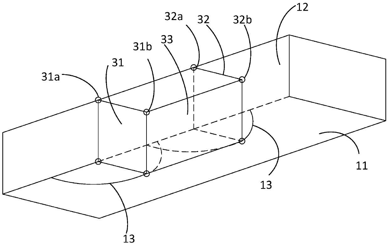
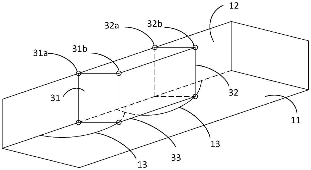
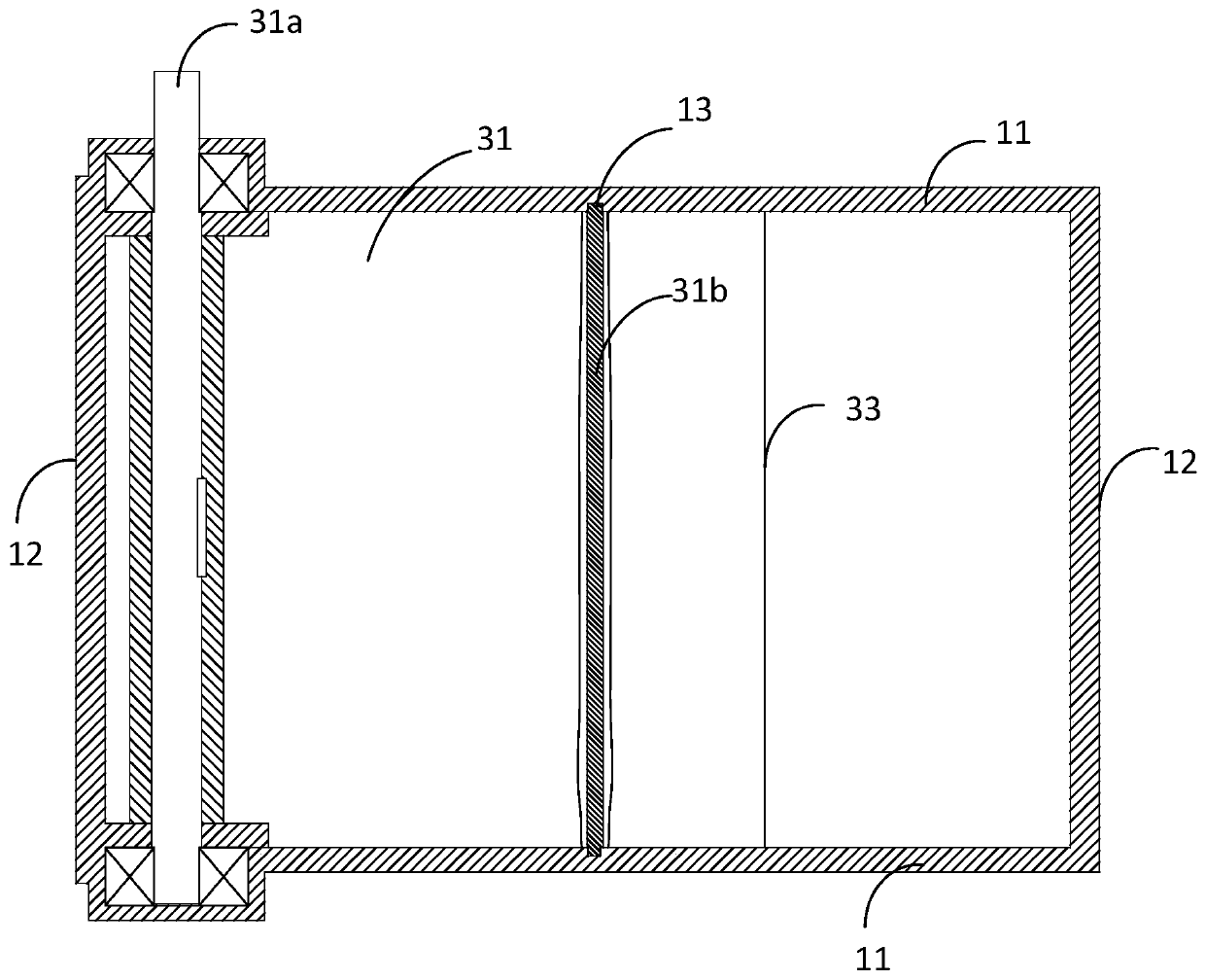
[0028] as attached figure 1 As shown, the embodiment of the present invention provides a rigid cross-sectional device, including a detection pipeline 1, a driving component and an execution component, the detection pipeline 1 is used for passing the fluid to be tested, and is made of rigid material; the driving component is used for the execution component Provide driving force; the actuator is connected to the power output end of the actuator, installed on the inner wall of the detection pipeline 1, and includes at least one deformation that can act under the action of the driving force to change the gap between the actuator and the installation wall The unit is used to change the internal cross-sectional area of the detection pipeline 1 by deforming the unit.
[0029] The detection pipeline 1 here can be made of a rigid material (such as a steel pipe), and the cross-section of the pipeline can be a general circular or square shape;
[0030] The deformation unit refers to ...
Embodiment 2
[0040] As a modification of the first embodiment above, see Figure 4 , the deformation unit includes an interference layer 37 and a deformable film layer 38; the interference layer 37 is arranged on the inner wall of the detection pipeline 1; the deformable film layer 38 connects the edge of the interference layer 37 and the inner wall of the detection pipeline 1, and the driving force acts Next, deformation occurs as the interference layer 37 approaches or moves away from the inner wall of the detection pipeline 1 in the radial direction; the interference layer 37, the deformable film layer 38, and the inner wall of the detection pipeline 1 covered by the interference layer 37 jointly form a sealed cavity 30; the detection pipeline 1 is provided with a through hole 301 communicating with the sealed cavity 30, and the through hole 301 is connected to the driving part 2 through a connecting pipe; the driving part 2 includes a gas source or a liquid source and is used for The i...
Embodiment 3
[0050] As another variation of Embodiment 1, see Figure 6-9 , the deformation unit also includes: two rectifying plates and two guide grooves; each rectifying plate is respectively located on the outside of an inner runner side plate, and one end of the two rectifying plates is hinged to both ends of the inner runner type panel (through The other ends of the two rectifying plates are respectively equipped with guide shafts; the two guide grooves are arranged on the cover plate of the detection pipeline, and are close to the adjacent side plates, and are respectively located on the sides of the two inner runners. The outer side of the whole formed by the connection of the inner runner plate and the inner runner type panel; one end of each guide shaft is located in a guide groove, and moves in the guide groove with the action of the inner runner type panel; the driving part includes a motor, and the motor The output shaft of the worm drive mechanism drives one of the inner chan...
PUM
 Abstract
Description
Claims
Application Information
 - R&D
- Intellectual Property
- Life Sciences
- Materials
- Tech Scout
- Unparalleled Data Quality
- Higher Quality Content
- 60% Fewer Hallucinations
Browse by: Latest US Patents, China's latest patents, Technical Efficacy Thesaurus, Application Domain, Technology Topic, Popular Technical Reports.
© 2025 PatSnap. All rights reserved.Legal|Privacy policy|Modern Slavery Act Transparency Statement|Sitemap|About US| Contact US: help@patsnap.com


