A device and method for three-way testing of field soil samples based on shear wave velocity

A testing device, shear wave technology, applied in measuring devices, using sound waves/ultrasonic waves/infrasonic waves to analyze solids, using sound waves/ultrasonic waves/infrasonic waves for material analysis, etc., can solve the cumbersome test methods and cannot completely reflect the original soil Anisotropy, Parallel Alignment of Piezoelectric Ceramics with Unbendable Elements, etc.

Active Publication Date: 2021-09-14
TONGJI UNIV
View PDF6 Cites 0 Cited by
  • Summary
  • Abstract
  • Description
  • Claims
  • Application Information

AI Technical Summary

Problems solved by technology

[0003] The commonly used test methods at this stage are relatively cumbersome and cannot fully reflect the original anisotropy of the soil. As a comprehensive index that can reflect the degree of compactness, stress state, and stress history of the soil, the shear wave velocity can be used to analyze the various properties of the soil. Anisotropy for a comprehensive description
In recent years, the bending element measurement system has become more and more popular in the measurement of shear wave velocity. It has the advantages of compact device, simple operation, and no damage to soil samples. However, its application range is mostly limited to indoors. When directly testing the newly obtained soil samples, it was found that the piezoelectric ceramics of a pair of bending elements could not be effectively aligned in parallel. In order to obtain the anisotropy of the soil in its natural state and avoid the influence on the anisotropy in the process of transportation and sample preparation, there is an urgent need for a device that can directly measure the wave velocity of the soil sample in the vertical and horizontal directions on site.

Method used


Image

  • A device and method for three-way testing of field soil samples based on shear wave velocity
  • A device and method for three-way testing of field soil samples based on shear wave velocity
  • A device and method for three-way testing of field soil samples based on shear wave velocity

Examples


Embodiment

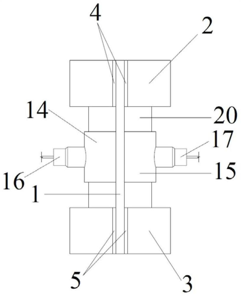
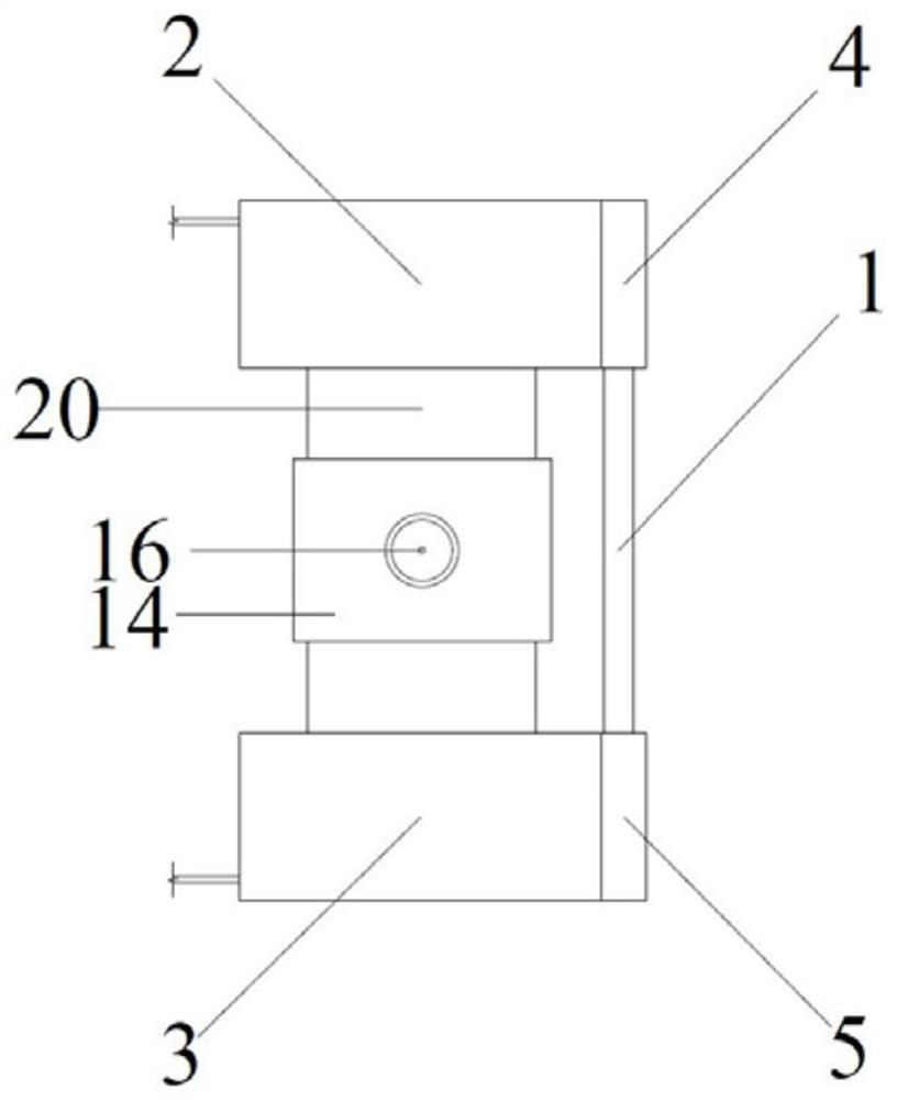
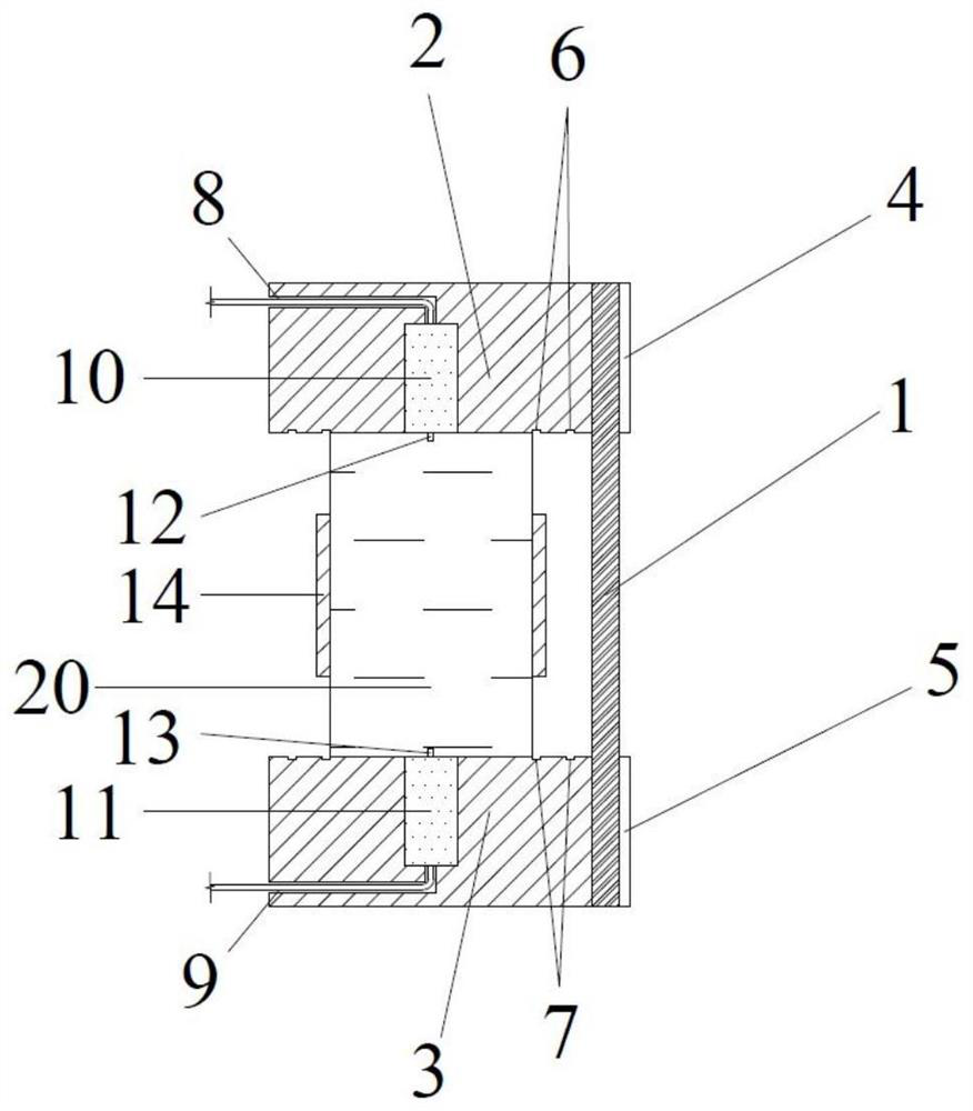
[0047] Such as figure 1 , figure 2 , image 3 As shown, a three-way test device for field soil samples based on shear wave velocity includes a positioning rod 1, a top hat 2 equipped with a bending element, a base 3 equipped with a bending element, and a split Die 14, split die 15 equipped with a bending element. The top cap 2 and the base 3 have the same structure, and their bodies are both cylindrical. The cross-section of the positioning rod 1 is a square with a side length of 10 mm, which is used to ensure that the top cap 2 and the base 3 maintain a correct positional relationship during use of the device. The split molds 14, 15 have the same structure, and their cross-sections are all semicircular.

[0048] The top cap 2 includes a bending element 10 , a positioning groove 4 , a circular groove 6 , and a cable channel 8 . The top hat 2 is made of steel, with a height of 55mm and a diameter of 120mm. A hole with a diameter of 20 mm and a depth of 40 mm is cut at t...


PUM

PropertyMeasurementUnit
heightaaaaaaaaaa
diameteraaaaaaaaaa

Abstract

The invention discloses a field soil sample three-way testing device and method based on shear wave velocity, which comprises a positioning rod, a pair of top hats and bases equipped with bending elements, and a pair of split molds equipped with bending elements. The positioning rod is external, and the material has high rigidity and basically no deformation; the top cap and the base are processed into certain sizes and specifications, and holes for installing bending elements are left in the center, and circular concave holes of uniform sizes are processed on the surface. The grooves are processed with positioning grooves of uniform size and specification on the side; the split mold is processed into a certain size and specification, and there is a hole for installing the bending element in the middle. Through this device, combined with the bending element measurement system, the three-dimensional wave velocity test of the soil sample can be carried out at the same time, and the anisotropy of the soil in the natural state can be obtained directly on the spot by using the difference of the three-dimensional wave velocity, which effectively improves the test efficiency. accuracy and convenience.

Description

technical field [0001] The invention relates to the field of field testing of geotechnical engineering. Background technique [0002] Although the soil mechanics analysis method based on the assumption of isotropy has been proved to be suitable for most practical projects, a large number of domestic and foreign studies have shown that considering the anisotropy of the soil can reflect the mechanical properties of the soil more truly. With the gradual improvement of my country's construction level, various major foundation projects have higher and higher requirements for deformation prediction and control, and the description of soil anisotropy has also received more and more attention in engineering design. [0003] The commonly used test methods at this stage are relatively cumbersome and cannot fully reflect the original anisotropy of the soil. As a comprehensive index that can reflect the degree of compactness, stress state, and stress history of the soil, the shear wave ...

Claims


Application Information

Patent Timeline
Patent Type & Authority Patents(China)
IPC IPC(8): G01N29/07G01N29/24
CPCG01N29/07G01N29/2437G01N2291/011G01N2291/023G01N2291/0422
Inventor 钱建固姜文澜顾晓强屠梓真
Owner TONGJI UNIV
Why Eureka
Try Eureka