An optical fiber adapter and an optical fiber connection structure

A technology of optical fiber adapter and optical fiber connector, which is applied in the direction of instruments, optics, light guides, etc., can solve problems such as large stress and damage to optical components, and achieve the effects of simple structure, improved yield rate, and convenient assembly

Active Publication Date: 2022-05-06
WUHAN UF OPTOELECTRIC TECH CO LTD
View PDF12 Cites 0 Cited by
  • Summary
  • Abstract
  • Description
  • Claims
  • Application Information

AI Technical Summary

Problems solved by technology

[0006] In order to solve the problem that existing optical fiber adapters tend to generate large stress due to axis misalignment when installing optical components, which in turn leads to damage to optical components, the purpose of the present invention is to provide an optical fiber adapter and an optical fiber connection structure

Method used


Image

  • An optical fiber adapter and an optical fiber connection structure
  • An optical fiber adapter and an optical fiber connection structure
  • An optical fiber adapter and an optical fiber connection structure

Examples


Embodiment 1

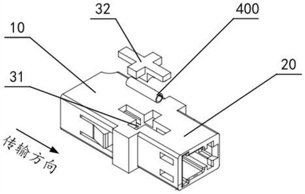
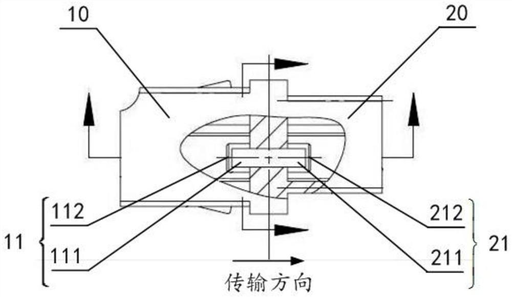
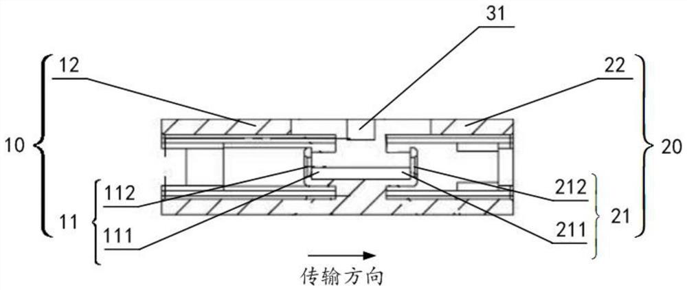
[0054] Such as Figure 1~3 As shown, the first fiber optic adapter provided in this embodiment includes an adapter body and an optical assembly 400, wherein the adapter body includes an adapter input end 10 and an adapter output end 20, and at the adapter input end 10 The input end alignment holder 11 including the input end receiving cavity 111 and the input end stopper 112 is provided at the place, and the output end 20 of the adapter is provided with the output end receiving cavity 211 and the output end stopper 212. The output end alignment holder 21; the contour body of the input end accommodation chamber 111 extends linearly toward the output side direction, and the contour body of the output end accommodation chamber 211 extends linearly toward the input side direction, so that the two contour bodies overlap to form a The integrated contour structure of the optical assembly 400 is accommodated, and an opening structure for loading the optical assembly 400 is provided on...

Embodiment 2

[0064] Such as Figure 4 As shown, on the basis of the technical solution of Embodiment 1, this embodiment provides another optical fiber adapter with a simplified structure, which defaults to the setting of the input port structural support 12 and the output port structural support 22, and only adds A circumferential body structure support 40 ensures the stability of the integral profile structure.

[0065] The technical effect of this embodiment can be directly derived by referring to the technical effect of the first embodiment, and will not be repeated here.

Embodiment 3

[0067] Such as Figure 5-7 As shown, this embodiment provides another fiber optic adapter on the basis of the technical solution of Embodiment 1. The end accommodating cavities 211 are all O-shaped accommodating cavities, and the opening structure is located at the input side end or output side end of the integrated contour structure and includes an end face opening and a stopper at the corresponding end, wherein the stopper The component is the input end stopper 112 or the output end stopper 212; the optical assembly 400 is installed into the integrated contour structure through the end face opening of the corresponding end and in an unobstructed state before setting the stopper , and then set the stopper connection on the socket profile on the corresponding side. Such as Figure 5-7 As shown, for example, before the output stopper 212 of the optical assembly 400 is set, since the end face opening at the output end is in an unobstructed state, it can be conveniently inserte...


PUM


Abstract

The invention relates to the technical field of optical fiber communication, and discloses an optical fiber adapter and an optical fiber connection structure, that is, by designing the contour body of the receiving cavity of the input end and the contour body of the receiving cavity of the output end into an integrated contour structure, the input end can be made The receiving chamber is connected with the receiving chamber at the output end and is integrally formed to prevent possible axis misalignment due to splicing, thereby reducing the risk of optical components being squeezed in the two receiving cavities, while ensuring that the optical components are in the receiving cavity It has a suitable floating space to ensure the assembly safety of optical components and improve the yield of products. In addition, through the integrated design of the alignment retainer and the port structure support, the J dimension in IEC-61754-20 can be guaranteed, so that when the optical fiber connector is inserted into the input end / output end of the adapter body, good docking efficiency can be obtained. Furthermore, stress can be avoided when the input end and / or output end are inserted, effectively preventing the loss of the connector from increasing, and improving the reliability of the product.

Description

technical field [0001] The invention relates to the technical field of optical fiber communication, in particular to an optical fiber adapter and an optical fiber connection structure. Background technique [0002] Existing fiber optic adapters (such as LC-type fiber optic adapters) cannot be made by the same process due to the differences in functions, materials or manufacturing processes between the optical components (such as collimating sleeves) and the parts of the adapter body. The components must be installed inside the adapter body. In order to solve this problem, the current fiber optic adapter is set to include two parts, the input end and the output end. After the optical components are installed in the cavity of the input end and the output end, the adapter is welded by ultrasonic welding. The input and output ends are welded together. [0003] However, the above-mentioned design has the following problems: when the adapter is fixed, the connector inserted into ...

Claims


Application Information

Patent Timeline
Patent Type & Authority Patents(China)
IPC IPC(8): G02B6/38
CPCG02B6/3825G02B6/389G02B6/3831
Inventor 张迪
Owner WUHAN UF OPTOELECTRIC TECH CO LTD
Why Eureka
Try Eureka