
Operation interlocking device of vacuum circuit breaker

A vacuum circuit breaker and interlocking device technology, which is applied to high-voltage air circuit breakers, circuits, electrical components, etc., can solve the problems of inability to open the gate, unfavorable user operation, and inability to operate the operating spindle.

Pending Publication Date: 2020-04-10
新机电器有限公司
View PDF0 Cites 0 Cited by
  • Summary
  • Abstract
  • Description
  • Claims
  • Application Information

AI Technical Summary

Problems solved by technology

When the vacuum circuit breaker is in operation, in order to ensure the safety of the operation, after operating the closing half shaft to rotate and close, the isolating switch and the grounding switch are both in the closing state, and the opening operation cannot be performed. After the isolating switch is opened, the opening operation of the isolating switch can be carried out. At the same time, when the isolating switch is in the closed state, the grounding switch cannot be opened. After the isolating switch is opened, the grounding switch can be opened. When the grounding switch is in the open state, the isolating switch and the closing half shaft cannot be operated, and when the isolating switch is in the open state, the operating spindle cannot be operated; at present, the vacuum circuit breaker usually adopts an interlocking structure to meet the above operating requirements, avoiding Misoperation can lead to safety accidents, but the existing interlock mechanism has a complex structure, a large number of parts, difficult installation and maintenance, and is not conducive to user operation.

Method used


Image

  • Operation interlocking device of vacuum circuit breaker
  • Operation interlocking device of vacuum circuit breaker
  • Operation interlocking device of vacuum circuit breaker

Examples


Embodiment Construction

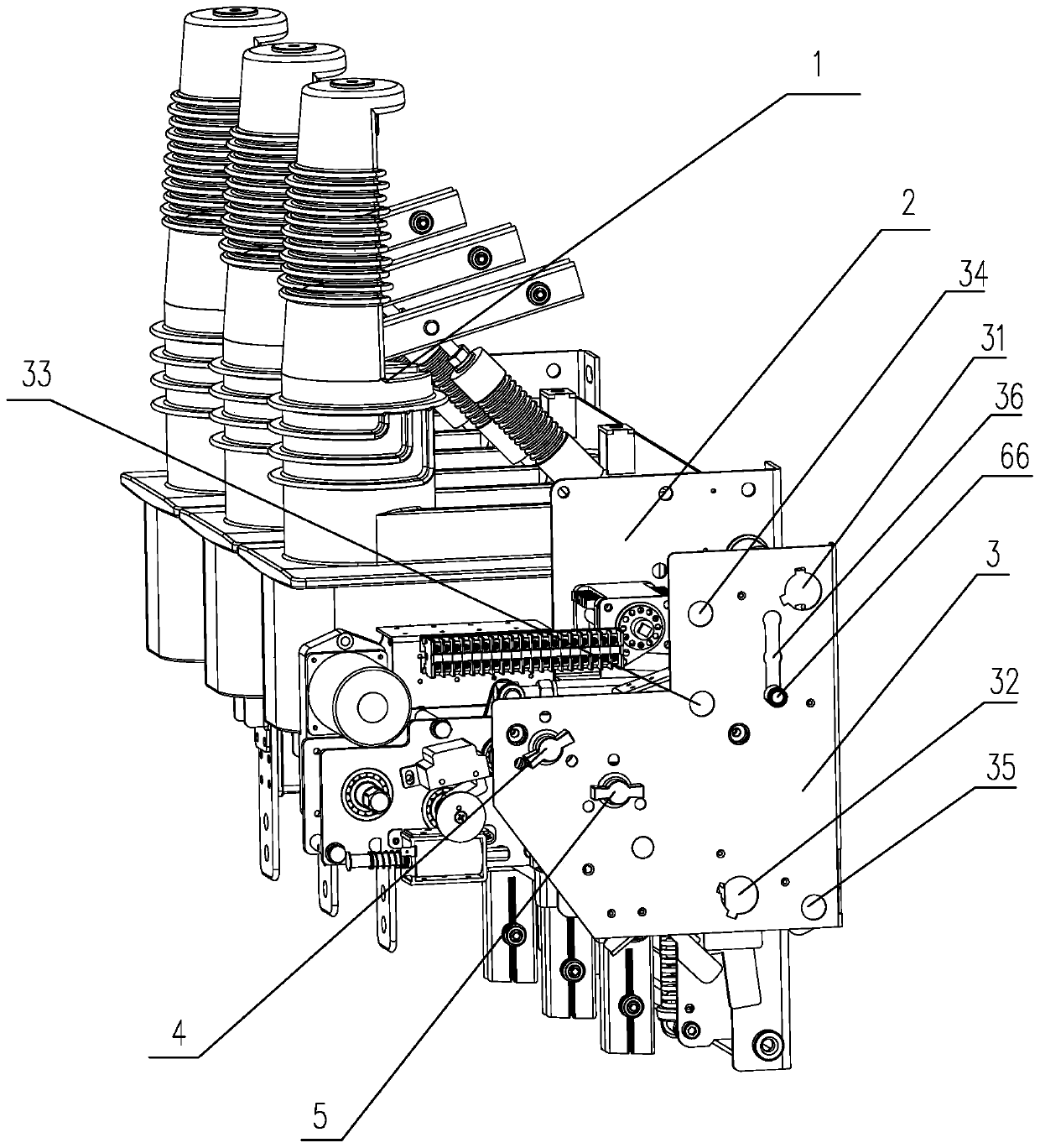
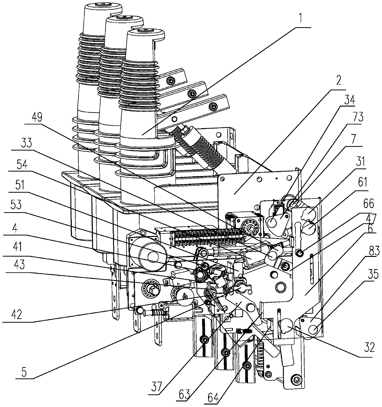
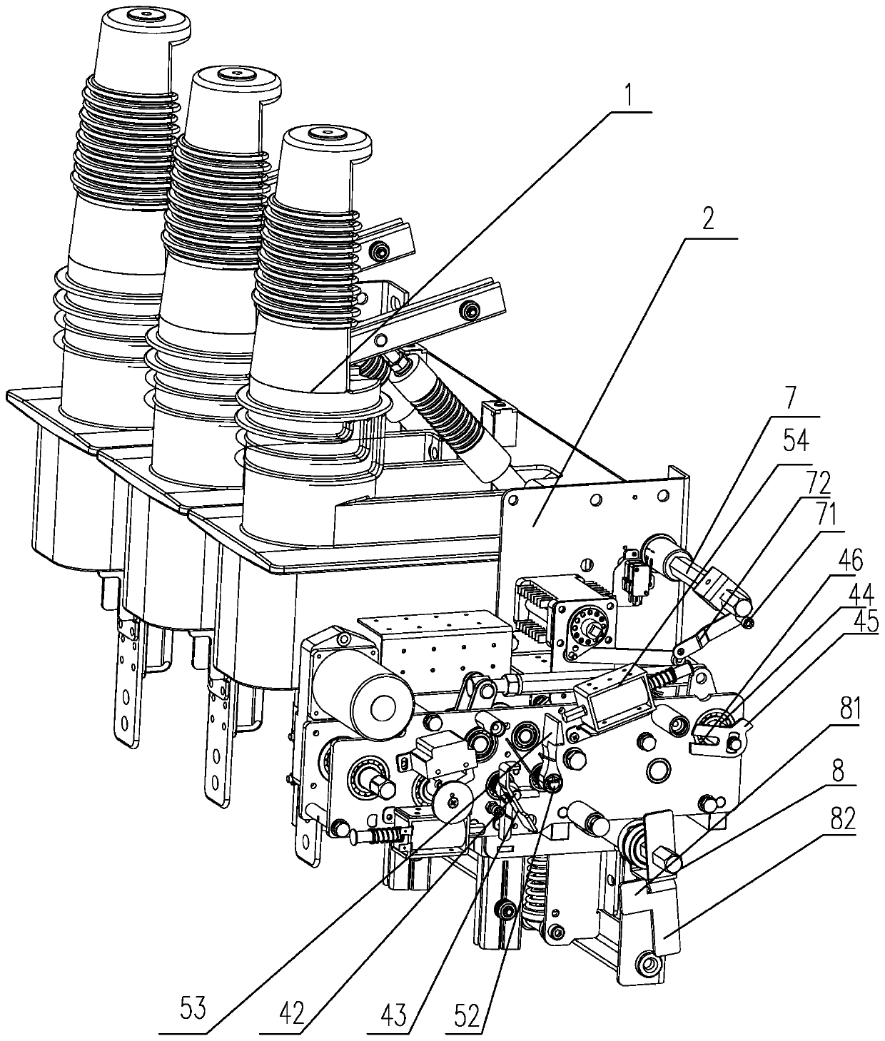
[0024] Depend on Figure 1 to Figure 4 Disclosed is an operation interlocking device for a vacuum circuit breaker, which includes a mounting frame 2 and a circuit breaker body 1, and the mounting frame 2 is rotatably provided with a closing half shaft 42, an opening half shaft 52, an isolation operation shaft 7, and a grounding operation shaft. Shaft 8, the mounting frame 2 is provided with a panel 3, the panel 3 is provided with a closing button 4 for operating the closing semi-axis 42, and the panel 3 is provided with a closing button 4 for operating the opening semi-axis 52 The opening button 5 for the opening operation, the panel 3 is respectively provided with an isolation window 31 and a grounding window 32 corresponding to the positions of the isolation operation shaft 7 and the grounding operation shaft 8, and the isolation window 31 is arranged above the grounding window 32, The closing button 4 and the opening button 5 are both arranged between the isolation window 3...


PUM


Abstract

The invention discloses an operation interlocking device of a vacuum circuit breaker. The operation interlocking device comprises a mounting rack and a breaker body, an opening half shaft, a closing half shaft, an isolation operation shaft and a grounding operation shaft are arranged in the mounting rack, and a panel is arranged on the mounting rack and is provided with a closing button and an opening button. The panel is also provided with an isolation window and a grounding window, a shielding plate is arranged on the panel in a sliding manner, and an isolation hole is formed at the position, corresponding to the isolation window, of the shielding plate. Limiting pieces are arranged between the closing button and the shielding plate and between the shielding plate and the closing buttonrespectively, a limiting stop block is arranged on the isolation operation shaft, and a first limiting protrusion is arranged on the shielding plate. A limiting arm is arranged on the grounding operation shaft, and a second limiting protrusion is arranged on the shielding plate. The operation interlocking device is simple and reasonable in structure, effectively realizes the interlocking among theisolation operation shaft, the grounding operation shaft, the closing half shaft and the opening half shaft, and ensures the overall safe use.

Description

technical field [0001] The invention relates to the technical field of vacuum circuit breakers, in particular to a small vacuum circuit breaker operation interlocking device. Background technique [0002] Vacuum circuit breaker is named for its arc extinguishing medium and the insulating medium of the contact gap after arc extinguishing are both high vacuum; it has the advantages of small size, light weight, suitable for frequent operation, and no maintenance for arc extinguishing. The application is more popular. When the existing vacuum circuit breaker is used, it mainly realizes power connection through the rotation of the closing semi-axis, and then realizes power-off through the rotation of the opening semi-axis. Of course, after the opening semi-axis rotates, it will drive the closing semi-axis to rotate and reset, which is convenient. One-time power-on and closing operation, and the opening half shaft will reset itself after completing the action. Other operation con...

Claims


Application Information

Patent Timeline
IPC IPC(8): H01H33/52H01H33/666H01H33/02H01H9/16
CPCH01H9/16H01H33/02H01H33/52H01H33/666
Inventor 潘巨源王金方柯昌伟
Owner 新机电器有限公司
Learn More