Supercharge Your Innovation With Domain-Expert AI Agents!

Tiltable antenna support

Antenna bracket, U-shaped technology, applied in the direction of antenna, antenna support/installation device, antenna parts, etc., can solve the problems of disassembly and assembly of antenna cable terminals, time-consuming and labor-intensive cutting construction, and inconvenient storage of antennas. Achieve the effect of reducing re-commissioning work, reducing time-consuming and labor-intensive operations, and convenient and practical operation

Pending Publication Date: 2020-04-10
CSSC XIJIANG SHIPBUILDING
View PDF0 Cites 2 Cited by
  • Summary
  • Abstract
  • Description
  • Claims
  • Application Information

AI Technical Summary

Problems solved by technology

The usual way is to disassemble the antenna that has been installed and debugged and put it on the deck, or cut or design the antenna bracket into a telescopic shape. These methods have great defects. The head is loose, the storage of the antenna is inconvenient, and the antenna needs to be re-installed, wired and debugged, resulting in repeated construction; the cutting construction is time-consuming and laborious; the telescopic antenna needs to be debugged again

Method used


Image

  • Tiltable antenna support
  • Tiltable antenna support
  • Tiltable antenna support

Examples


Embodiment Construction

[0012] The present invention will be described in detail below in conjunction with the accompanying drawings and embodiments.

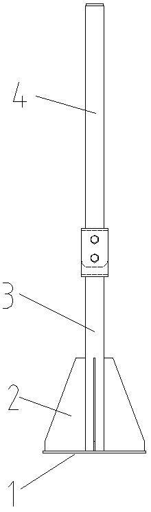
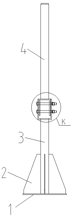
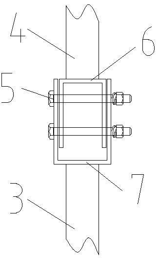
[0013] Such as Figure 1 ~ Figure 4 As shown, a tiltable antenna bracket of the present invention includes a base plate 1 and a column, the column is vertically connected to the base plate 1, and a reinforcing rib 2 is arranged at the connection, the reinforcing rib 2 is connected to the column and the base plate 1, and the column includes an upper Upright column 4 and lower column 3, the lower end of upper column 4 is connected with U-shaped flange plate I6 with the opening facing downward, and the upper end of lower column 4 is connected with U-shaped flange plate II7 with opening facing upward, U-shaped flange plate I6 and The U-shaped flanged plates II7 are movably socketed with each other and are detachably connected by at least two sets of bolts 5 .

[0014] When the present invention is actually implemented, the U-shaped flange I6 is welded to...


PUM


Abstract

The invention discloses a tiltable antenna support. The tiltable antenna support comprises a bottom plate and a stand column, and the stand column is perpendicularly connected to the bottom plate. A reinforcing rib plate is arranged at the joint, the stand column comprises an upper stand column body and a lower stand column body, the lower end of the upper stand column body is connected with a U-shaped folded edge plate I with a downward opening, the upper end of the lower stand column body is connected with a U-shaped folded edge plate II with an upward opening, and the U-shaped folded edge plate I and the U-shaped folded edge plate II are movably connected in a sleeved mode and detachably connected through at least two sets of bolts. The antenna support is simple in structure, convenientand practical to operate and capable of being rapidly toppled over, and an antenna does not need to be debugged again.

Description

technical field [0001] The invention relates to the technical field of ship equipment, in particular to a tiltable antenna support for ships. Background technique [0002] Antenna is an important component of ship equipment. The antenna on the ship can provide a variety of information and entertainment signals for the ship, which is of great significance to ensure the safety of ship navigation and improve the navigation environment. The antenna is usually installed on the antenna bracket and installed on the top deck of the ship. Some wireless devices are equipped with longer antennas. Due to the height limit requirements of the channel, the over-high antenna needs to be turned down before the ship sails to avoid the top of the antenna. The antenna is damaged due to a collision with the bridge, and it must be erected after passing the bridge or the height-limited waterway. The usual way is to disassemble the antenna that has been installed and debugged and put it on the dec...

Claims


Application Information

Patent Timeline
IPC IPC(8): H01Q1/12
CPCH01Q1/1235
Inventor 刘荣
Owner CSSC XIJIANG SHIPBUILDING
Features
  • R&D
  • Intellectual Property
  • Life Sciences
  • Materials
  • Tech Scout
  • Unparalleled Data Quality
  • Higher Quality Content
  • 60% Fewer Hallucinations
Learn More