
Underground pump room inlet sealing device and pouring method thereof

A closed device and pump room technology, which is applied to the suspension device of the wing fan, the layout of the wing fan, the building components, etc., can solve the problems of unsafe opening and closing, unsafe access to things, etc., to achieve good water permeability and improve service life. Effect

Inactive Publication Date: 2020-04-14
四川中至耀辉建设有限公司
View PDF8 Cites 0 Cited by
  • Summary
  • Abstract
  • Description
  • Claims
  • Application Information

AI Technical Summary

Problems solved by technology

[0002] Most of the entrances of traditional underground pump rooms are open, and it is not safe to drop things during use, and most of the existing covers are made of steel plates or wooden boards, which are not easy to open and close.

Method used


Image

  • Underground pump room inlet sealing device and pouring method thereof
  • Underground pump room inlet sealing device and pouring method thereof
  • Underground pump room inlet sealing device and pouring method thereof

Examples


Embodiment 1

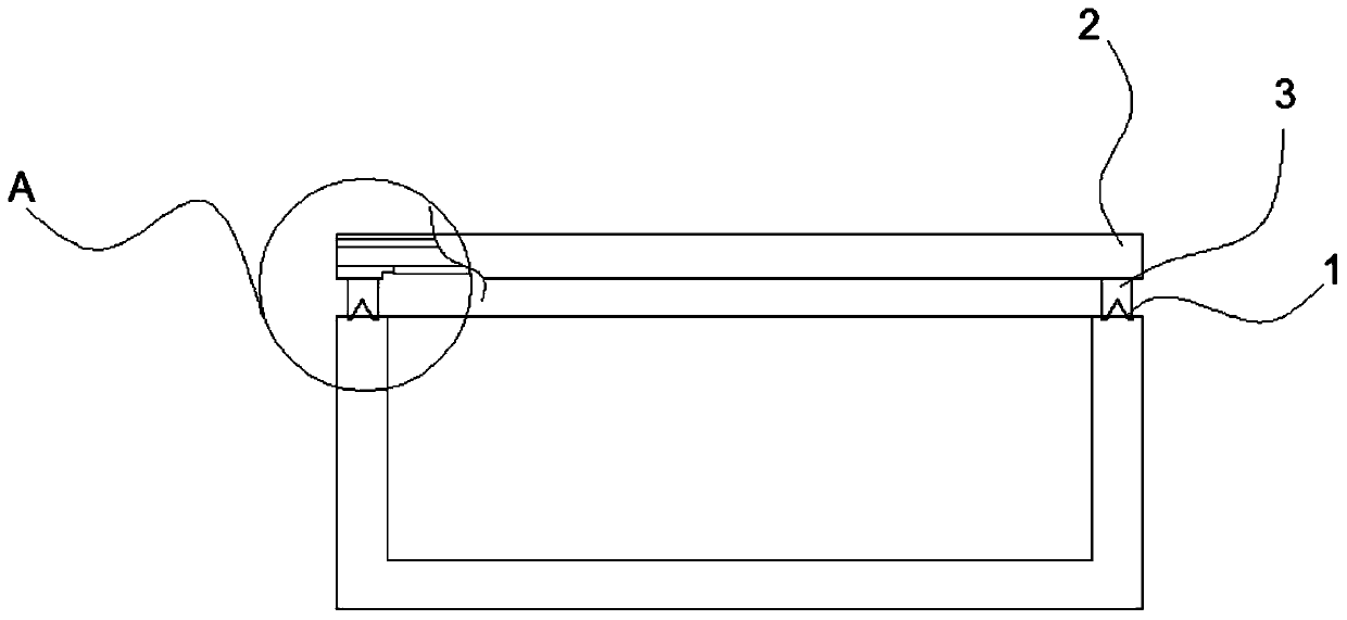
[0037] Such as Figure 1-3 As shown, a closed device for the entrance of an underground pump room includes a slide rail 1, a package plate 2 and a directional pulley 3. The slide rail 1 is pre-buried on both sides of the top of the entrance and exit of the underground pump room. The length is less than or equal to 1 / 2 of the length on both sides of the entrance and exit of the underground pump room, the packaging plate 2 is matched with the entrance of the underground pump room, the directional pulley 3 is installed on one side of the packaging plate 2, the Orientation pulley 3 cooperates with described slide rail 1.

[0038] A slide rail 1 is set at the entrance of the underground pump room, and a directional pulley 3 matched with the slide rail 1 is provided on the package plate 2 for the purpose of opening or closing the entrance of the underground pump room conveniently, and the length of the slide rail 1 is set in the underground 1 / 2 the length of the pump inlet is to ma...

Embodiment 2

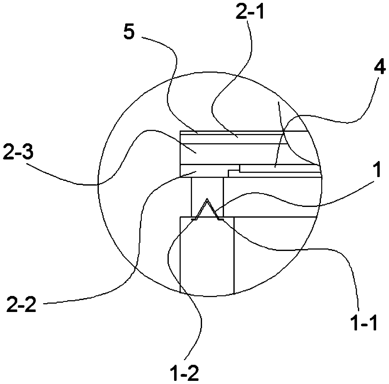
[0040] Such as Figure 1-3 As shown, this embodiment is based on Embodiment 1, and the bottom of the packaging board 2 is provided with a reinforcing rib 4 . The reinforcing rib 4 is provided at the bottom of the packaging board 2 to enhance the strength of the packaging board 2 .

Embodiment 3

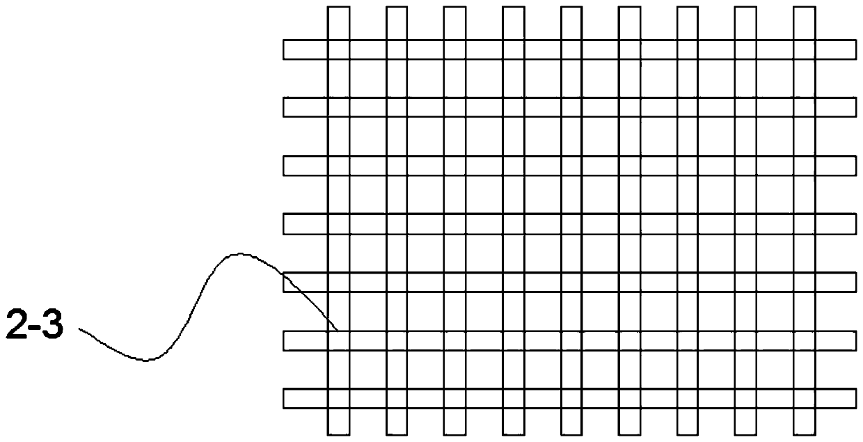
[0042] Such as Figure 1-3 As shown, this embodiment is based on Embodiment 1, the packaging board 2 includes a top board 2-1 and a bottom board 2-2, and a reinforcing frame 2-3 is provided between the top board 2-1 and the bottom board 2-2 .

[0043] The packaging board 2 includes a top board 2 - 1 and a bottom board 2 - 2 , and a reinforcing frame 2 - 3 is arranged between the top board 2 - 1 and the bottom board 2 - 2 to improve the strength of the whole packaging board 2 .


PUM

PropertyMeasurementUnit
Diameteraaaaaaaaaa
Diameteraaaaaaaaaa

Abstract

The invention discloses an underground pump room inlet sealing device. The underground pump room inlet sealing device comprises sliding rails, a packaging plate and directional pulleys, wherein the sliding rails are embedded in the two sides of the top of an inlet and outlet of an underground pump room; the length of the sliding rails is smaller than or equal to 1 / 2 of the length of the two sidesof the inlet and outlet of the underground pump room; the packaging plate is matched with the inlet of the underground pump room; and the directional pulleys are installed on one side of the packagingplate and matched with the sliding rails. The sliding rails are arranged at the inlet of the underground pump room, the packaging plate is provided with the directional pulleys matched with the sliding rails so that the inlet of the underground pump room can be conveniently opened or closed, and meanwhile, the length of the sliding rails is set to be 1 / 2 of the length of the inlet of the underground pump room so that the underground pump room can be more attractive. The invention further discloses a pouring method of the underground pump room inlet sealing device.

Description

technical field [0001] The invention relates to the technical field of construction, in particular to a sealing device for an entrance of an underground pump room and a pouring method thereof. Background technique [0002] Most of the entrances of traditional underground pump houses are open, and it is not safe to drop things during use, and most of the existing covers are made of steel plates or wooden boards, which cannot be opened and closed conveniently. Contents of the invention [0003] In order to solve the problems existing in the prior art, the present invention provides a sealing device for the entrance of an underground pump house and a pouring method thereof, which have the advantages of simplifying the external structure and increasing the overall strength. [0004] In order to achieve the above object, the technical solution adopted by the present invention is: a closed device for the entrance of an underground pump room, including slide rails, packaging plat...

Claims


Application Information

Patent Timeline
IPC IPC(8): E06B5/02E06B3/46E05D13/00E06B3/70C04B28/04B28B1/14
CPCB28B1/14C04B28/04E05D13/00E06B3/46E06B3/70E06B5/02E06B2003/7049C04B2103/302C04B14/068C04B22/002
Inventor 李少虎
Owner 四川中至耀辉建设有限公司
Learn More