Resistance-adjustable shock absorber for automobile

An adjustable shock absorber technology, applied in the direction of shock absorber, shock absorber-spring combination, shock absorber, etc., can solve the problem that the resistance-adjustable shock absorber is not reset smoothly, reduces the oil flow resistance, and affects the automobile. performance and other issues, to avoid the increase in oil temperature, improve the quality of work, and improve the effect of shock absorption

Active Publication Date: 2020-04-14
NANJING INST OF TECH
View PDF6 Cites 4 Cited by
  • Summary
  • Abstract
  • Description
  • Claims
  • Application Information

AI Technical Summary

Problems solved by technology

When the position of the plunger relative to the orifice on the hollow connecting rod reaches the beginning of plugging, the channel cross-sectional area of ​​the orifice begins to decrease, so the amount of liquid passing through the orifice decreases, which increases the flow resistance of the oil. When the load decreases, the plunger moves upwards, and the channel interception area of ​​the orifice increases, which reduces the flow resistance of the oil. However, after the resistance adjustable shock absorber is used for a long time, the temperature of the oil and the cylinder due to friction will increase. Under the effect of high temperature, the oil will cause high temperature impact on other structures inside the cylinder, and at the same time affect the effect of shock absorption. At the same time, after long-term use, due to friction, the reset of the adjustable resistance shock absorber will often be unsmooth. , the phenomenon of half-resetting or jamming will seriously affect the performance of the car, so we propose a resistance-adjustable shock absorber for cars

Method used


Image

  • Resistance-adjustable shock absorber for automobile
  • Resistance-adjustable shock absorber for automobile
  • Resistance-adjustable shock absorber for automobile

Examples


Embodiment Construction

[0021] The following will clearly and completely describe the technical solutions in the embodiments of the present invention with reference to the accompanying drawings in the embodiments of the present invention. Obviously, the described embodiments are only some, not all, embodiments of the present invention.

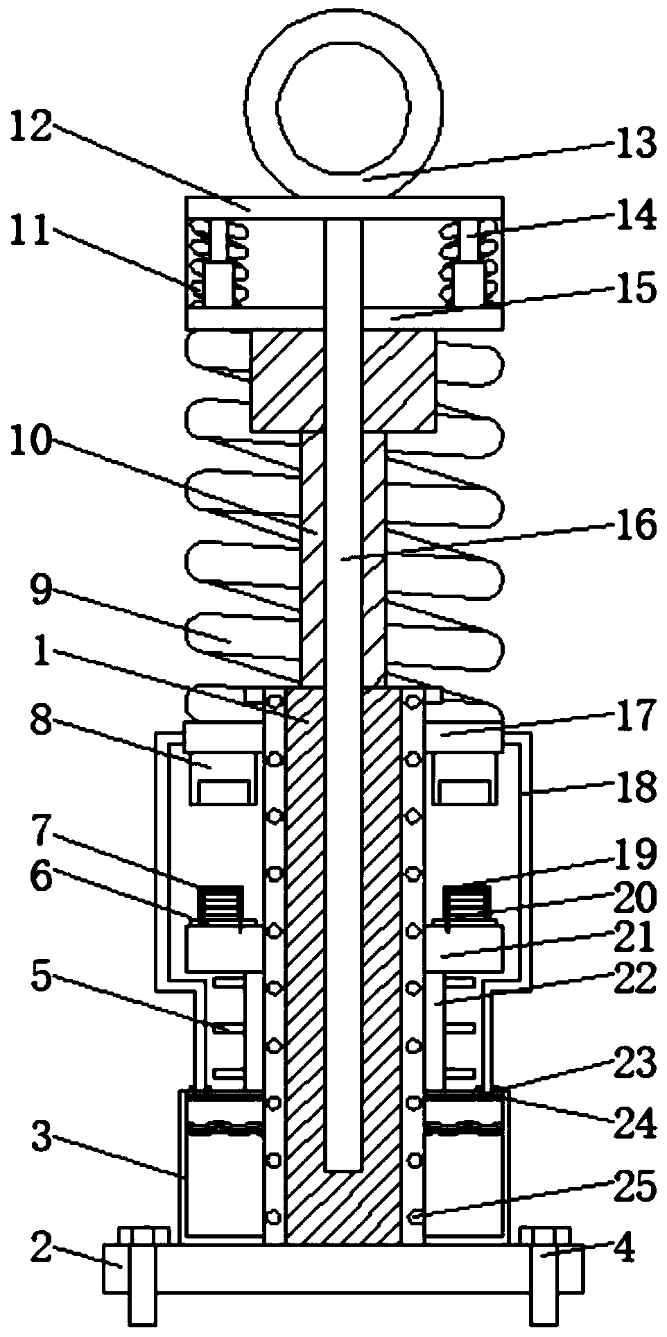
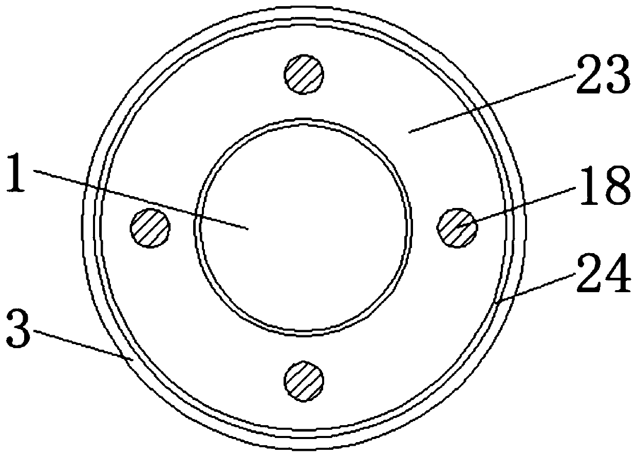
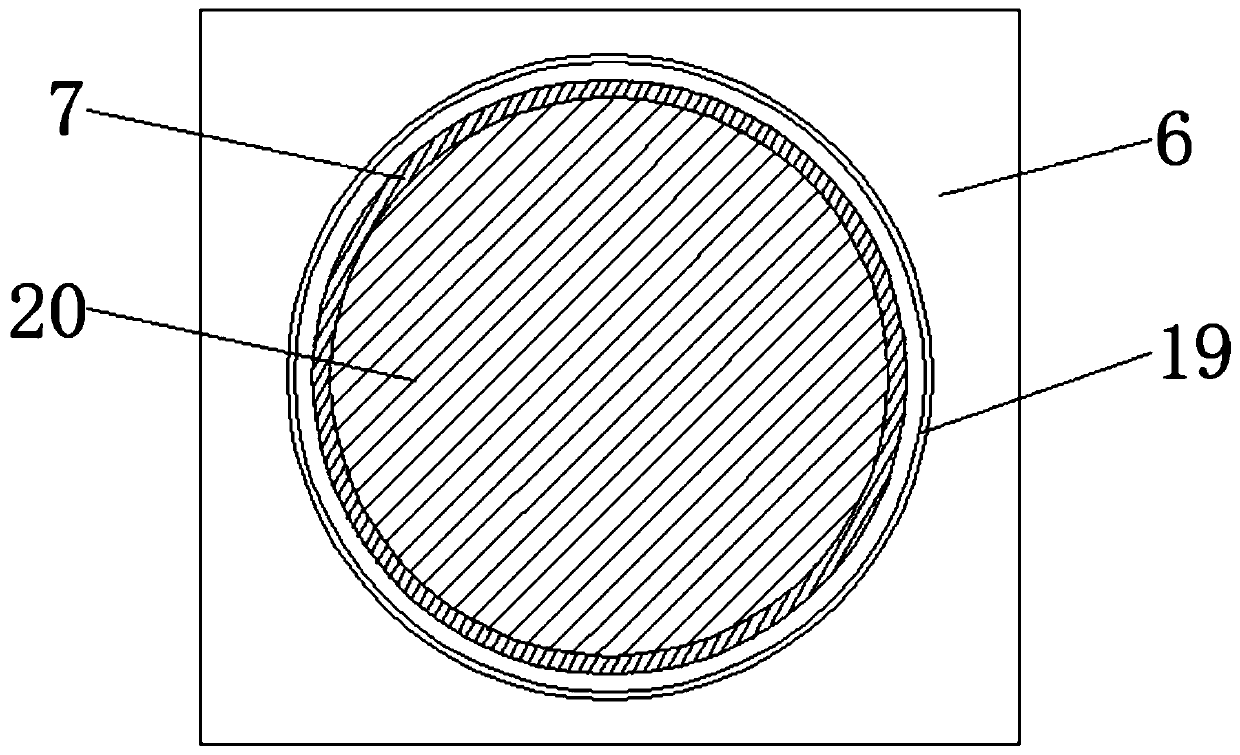
[0022] see Figure 1 to Figure 4, the present invention provides a technical solution: a resistance adjustable shock absorber for automobiles, comprising a resistance adjustable shock absorber sleeve body 1, the inner cavity of the resistance adjustable shock absorber sleeve body 1 is movably socketed with a hollow The sleeve rod 10, the inner cavity of the hollow sleeve rod 10 is movably sleeved with a plunger rod body 16, one end of the plunger rod body 16 is fixedly connected to the lower surface of the top plate 12, and the top of the hollow sleeve rod 10 is fixedly connected with a support plate 15, Both sides of the upper surface of the support plate 15 are fix...


PUM


Abstract

The invention discloses a resistance-adjustable shock absorber for an automobile, relates to the technical field of shock absorbers, and particularly relates to a resistance-adjustable shock absorberfor an automobile. The resistance-adjustable shock absorber comprises a resistance-adjustable shock absorber sleeve body, wherein a hollow sleeve rod is movably sleeved in an inner cavity of the resistance-adjustable shock absorber sleeve body, and a supporting plate is fixedly connected to the top of the hollow sleeve rod. According to the resistance-adjustable shock absorber for the automobile,through the cooperative use of a movable plate, auxiliary shock-absorbing springs and the supporting plate, auxiliary shock absorption is conducted through the auxiliary shock absorbing springs on thebasis that an original resistance-adjustable shock absorber for an automobile adapts to oil pressure shock absorption, the problem that the resistance-adjustable shock absorber for the automobile isdamaged due to stress under the condition of huge vibration is solved, the shock absorption effect of the resistance-adjustable shock absorber for the automobile can be improved at the same time, theplunger rod body is assisted in resetting, and the working quality of the resistance-adjustable shock absorber for the automobile is improved.

Description

technical field [0001] The invention relates to the technical field of shock absorbers, in particular to a shock absorber with adjustable resistance for automobiles. Background technique [0002] The resistance-adjustable shock absorber cylinder is equipped with a piston, and a hollow connecting rod is installed in the middle hole of the piston. The upper end of the hollow connecting rod is fixed on the lower shell of the air chamber, and a plunger rod and a plunger are also installed in the hollow connecting rod. The upper end of the plunger rod leans against the spring seat and the diaphragm. A spring is installed between the spring seat and the plunger rod. The lower end of the hollow connecting rod is provided with an orifice close to the upper surface of the piston, and the resistance can be adjusted. The shock absorber is used on the suspension whose elastic element is an air spring. When working, as the load of the vehicle increases, the air pressure in the air spri...

Claims


Application Information

Patent Timeline
Patent Type & Authority Applications(China)
IPC IPC(8): F16F9/42F16F9/36F16F9/32F16F13/00B60G13/08B60G13/04
CPCB60G13/04B60G13/08F16F9/3207F16F9/369F16F9/42F16F13/007F16F2222/025F16F2222/12F16F2238/026
Inventor 赵振东
Owner NANJING INST OF TECH
Why Eureka
Try Eureka