An on-axis component installation and cooperation structure

A matching structure and component installation technology, applied in the direction of couplings, engine components, rigid shaft couplings, etc., can solve problems such as complex design and constraint design, and achieve the effect of avoiding force damage

Inactive Publication Date: 2019-05-07
姜开春
View PDF3 Cites 0 Cited by
  • Summary
  • Abstract
  • Description
  • Claims
  • Application Information

AI Technical Summary

Problems solved by technology

While such methods are effective, they are relatively complex to design and also constrain the design of complex machinery such as turbochargers

Method used


Image

  • An on-axis component installation and cooperation structure
  • An on-axis component installation and cooperation structure
  • An on-axis component installation and cooperation structure

Examples


Embodiment Construction

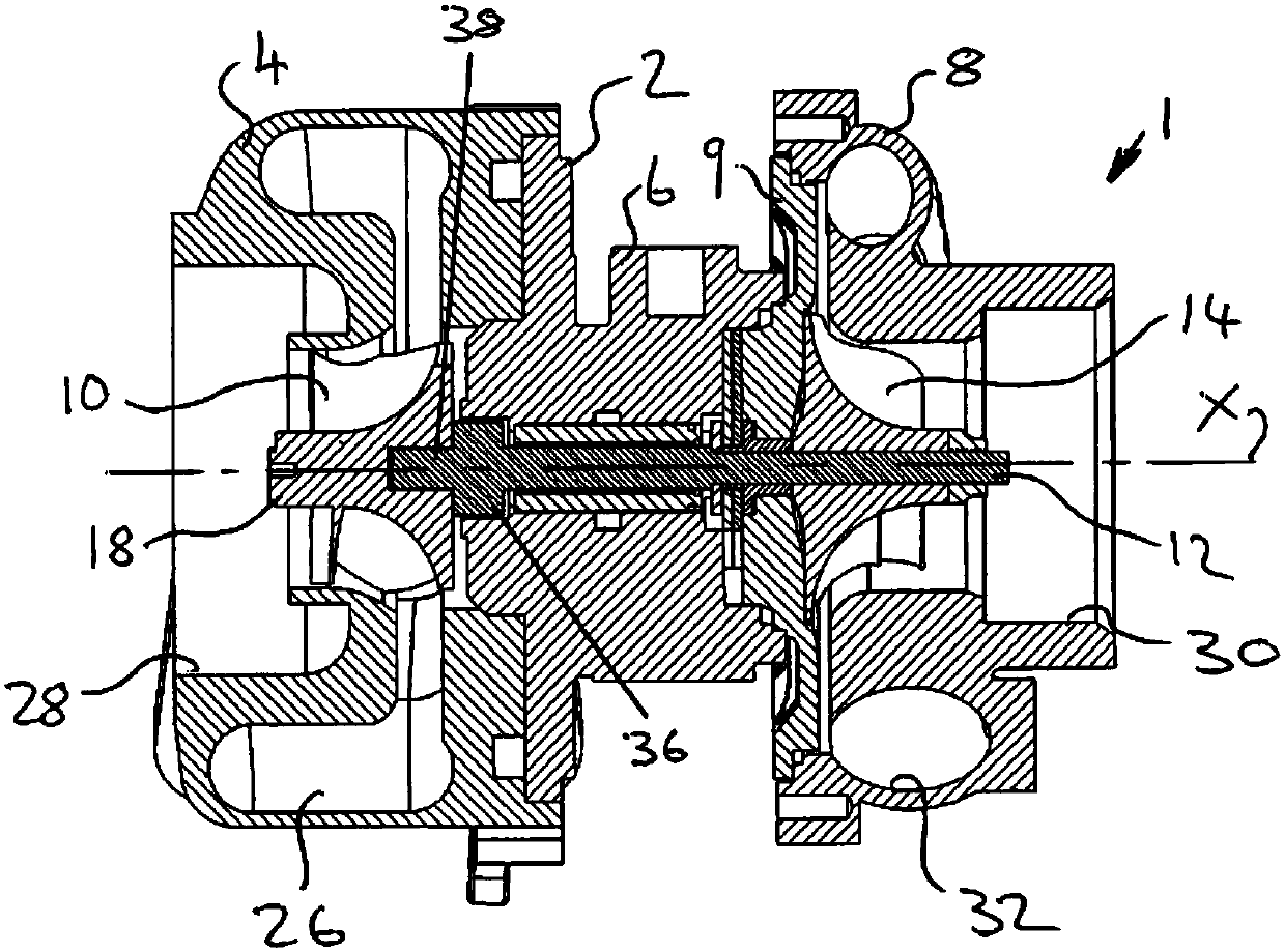
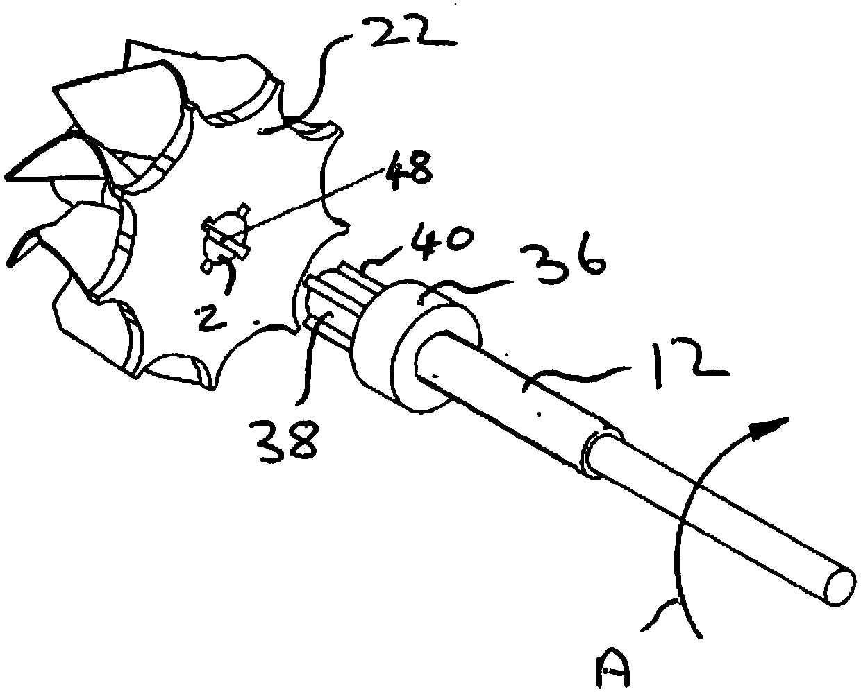
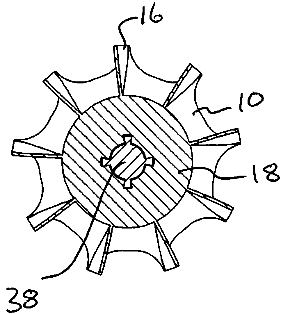
[0042] The installation and cooperation structure of the on-axis component of the present invention is as follows: an on-axis component that can rotate at a high speed and is installed on the shaft and rotates together with the shaft along the longitudinal axis of the shaft; the on-axis component has a surface that defines A central axial hole is at least partially passed through; the shaft component also includes at least 2 longitudinal keyways in the surface of the central axial hole, each keyway has an anterior surface and a caudal surface; the shaft A part extends into said central axial hole, the outer peripheral surface of this part of the shaft has a number of longitudinal keys corresponding to the number of key slots, each key has a front side surface and a tail side surface, and the keys fit into the corresponding key slots to form Key / keyway combinations; wherein, at least at room temperature, the keyways are wider than the keys, and each key is circumferentially offs...


PUM


Abstract

The component has an axial bore (20 fig. 5) with at least two longitudinal keyways 48. The shaft has a corresponding number of longitudinal keys 40, each key being received in a respective keyway to form a key / keyway combination 56', 56". The keyways are wider than the keys and each key is circumferentially offset relative to its respective keyway. At least one key / keyway combination (e.g. 56) is offset such that the leading side surfaces of the key and keyway abut one other and a clearance 58 is provided between their trailing side surfaces. At least one other key / keyway combination (e.g. 56") is offset such that the trailing side surfaces of the key and thekeyway abut one another and a clearance 60 is provided between their leading side surfaces. Further clearances 62 may be provided between the radially outer surfaces of the keys and the keyways. The component may be a turbine wheel for a turbocharger and may allow for thermal expansion of the components during use.

Description

technical field [0001] The invention belongs to the technical field of mounting components on mechanical shafts, and relates to a mounting and matching structure, in particular to a mounting and matching structure of components on a shaft, which is especially suitable for products similar to turbochargers. Background technique [0002] As is known, a turbocharger takes in hot exhaust gas from an internal combustion engine and converts the energy contained in the exhaust gas into kinetic energy (rotation) by means of a turbine wheel mounted on an axial, rapidly rotating shaft. The turbine wheel imparts rotational motion along the shaft to rotate a compression wheel that draws air into the turbocharger and compresses the air to supply the engine's cylinders through the inlet manifold. The turbocharger used can greatly increase the overall efficiency of the internal combustion engine. An important consideration in turbocharger design includes reducing energy loss to maximize e...

Claims


Application Information

Patent Timeline
Patent Type & Authority Patents(China)
IPC IPC(8): F02B39/00F01D25/28
CPCF16D1/101F01D5/025F05D2220/40F16D1/0858F16D2001/102
Inventor 姜开春
Owner 姜开春
Why Eureka
Try Eureka