A spin-mixed magnetorheological fluid high-speed shock absorber and a swirling mixing method for the magnetorheological fluid

A magneto-rheological fluid and rheological fluid technology, applied in the field of mechanical vibration reduction, can solve the problems of reducing the service life of the buffer, uneven force, prone to precipitation, etc., and achieve the effect of prolonging the service life

Active Publication Date: 2021-03-12
ZHUZHOU TIMES NEW MATERIALS TECH
View PDF6 Cites 0 Cited by
  • Summary
  • Abstract
  • Description
  • Claims
  • Application Information

AI Technical Summary

Problems solved by technology

However, in practical applications, the magnetorheological fluid used as a damping fluid, the magnetically sensitive particles formed by the mixture of silicon oil and iron ions contained in it, tend to precipitate in the magnetorheological fluid, resulting in too much accumulation at the bottom of the damping cylinder during the impact process. The magneto-inductive particles make the magnetorheological fluid pass through the gap between the piston and the damping cylinder during the damping process to receive the magnetic field magnetorheological action, the magnetorheological fluid in the lower gap becomes too thick, and the magnetorheological fluid in the upper gap The liquid is obviously thinner, resulting in uneven force during the piston movement, which not only directly reduces the vibration damping effect, but also significantly reduces the service life of the buffer

Method used


Image

  • A spin-mixed magnetorheological fluid high-speed shock absorber and a swirling mixing method for the magnetorheological fluid
  • A spin-mixed magnetorheological fluid high-speed shock absorber and a swirling mixing method for the magnetorheological fluid
  • A spin-mixed magnetorheological fluid high-speed shock absorber and a swirling mixing method for the magnetorheological fluid

Examples


Embodiment Construction

[0027] The present invention will be further described below with reference to the drawings:

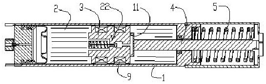
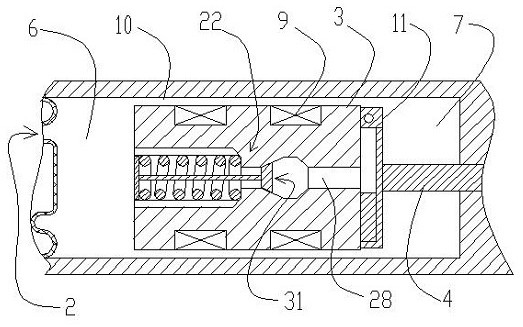
[0028] Such as figure 1 , 2 , 7, a spin magnetic flow soot high-speed damper, including the damper body 1, damping cylinder 2, piston 3, push rod 4 and reset spring 5; disposing damping cylinder on the damper body The piston 3 is located in the damper cylinder 2, separating the damper cylinder 2 as the front compression chamber 6 and the rear pressure chamber 7; the piston is provided with a mosaic slot 8 inlaid, in the inlay groove 8, in the inlay groove 8 The coil 9; the piston 3 and the electromagnetic coil 9 in the piston are in the inner wall of the damper cylinder 2, and one end of the push rod 4 is connected to the piston 3 in the damper cylinder 2, and the other end projects out of the damper cylinder 2. The reset spring 5 is provided on the push rod 4 outside the damper cylinder 2, and the piston 3 is located at one end of the backbound chamber 7, which is provided with a swirl...


PUM


Abstract

The invention discloses a spin-mixing magnetorheological fluid high-speed shock absorber and a magnetorheological fluid rotational flow mixing method thereof. The shock absorber comprises a damping cylinder for pouring a magnetorheological fluid, a piston and a push rod, wherein the piston is located in the damping cylinder, the damping cylinder is divided into a forward pressure cavity at the front part and a reverse pressure cavity at the back part, the end, located at the reverse pressure cavity, of the piston is provided with a rotational flow spray disc, and the edge of the rotational flow spray disc is provided with a tangential spray hole; a one-way valve flow control channel is arranged in the piston, and a liquid inlet of the one-way valve flow control channel is located at the end, located at forward pressure cavity, of the piston; and an outlet of the one-way valve flow control channel communicates with the tangential spray hole of the rotational flow spray disc, when the impact is encountered, a push rod pushes the piston to extrude the magnetorheological fluid in the forward pressure cavity, part of the magnetorheological fluid is forced to be directly sprayed out fromthe tangential spray hole of the rotational flow spray disc through the one-way valve flow control channel, so that the magnetorheological fluid forms a rotational flow in the reverse pressure cavity. The shock absorber has the advantages that magnetic induction particles of the magnetorheological fluid in a buffer are uniformly distributed in the magnetorheological fluid, so that the buffer is always in the optimal vibration damping state.

Description

Technical field [0001] The present invention relates to a rotary magnetoelectric high speed damper, which belongs to the field of mechanical damping technology. Background technique [0002] In high-speed impact environments, the mechanical system can resist the instantaneous impact of the structure, and the buffer has always played a huge role. The basic principle of the buffer is that the bidirectional reverse damping stroke converts the impact kinetic energy into thermal energy, ie the shock damping stroke and the reverse reset damping stroke. When encountering an impact, the powerful impact force pushes the piston in the damping liquid in the damper cylinder. The powerful kinetic energy is partially absorbed into thermal energy, and the kinetic energy can be The reset spring is stored in the form of a reset spring is compressed into an elastic potential energy; when the impact is completed, the compressed reset spring will force the push rod to push the piston in the damper c...

Claims


Application Information

Patent Timeline
Patent Type & Authority Patents(China)
IPC IPC(8): F16F9/53
CPCF16F9/535F16F9/537
Inventor 胡小刚周海军涂奉臣张弯弓王里达刘少文贺才春
Owner ZHUZHOU TIMES NEW MATERIALS TECH
Why Eureka
Try Eureka