Dynamic flame forming method, flame simulation structure and electronic candle

A simulation structure and dynamic technology, applied in the field of flame simulation, can solve the problems such as the increase of fidelity of electronic candle flame simulation, the inability of the flame sheet to swing normally, and the inability to form a swaying flame, so as to reduce the production cost and process difficulty, short torque, simple structure

Inactive Publication Date: 2020-04-14
FOSHAN MOGEN INTELLIGENT TECH CO LTD
View PDF0 Cites 1 Cited by
  • Summary
  • Abstract
  • Description
  • Claims
  • Application Information

AI Technical Summary

Problems solved by technology

[0003] Existing electronic candles only project a single light and shadow to simulate flames, but flames usually have outer flames and inner flames, and existing electronic candles do not have the function of simulating outer flames and inner flames at the same time, so the fidelity of electronic candle flame simulation has a lot of room to grow
[0004] In addition, existing electronic candles still have disadvantages such as high energy consumption and limited placement angles.
For example, when the electronic candle is placed obliquely, there may be technical problems such as the failure of the swing mechanism and the failure of the flame sheet to swing normally, resulting in the inability to form a swaying flame

Method used


Image

  • Dynamic flame forming method, flame simulation structure and electronic candle
  • Dynamic flame forming method, flame simulation structure and electronic candle
  • Dynamic flame forming method, flame simulation structure and electronic candle

Examples


Embodiment 1

[0056] This embodiment provides a method for forming a dynamic flame, in which the light emitted by several groups of light sources is respectively projected onto the flame sheet; wherein, at least one group of light sources is used as the inner flame light source, and the inner flame projection light and shadow formed by the inner flame light source on the flame sheet occur The dynamic inner flame is formed by changing position and / or alternation of light and shade; using at least one group of light sources whose luminous color is different from that of the inner flame light source as the outer flame light source, and the outer flame projection light and shadow formed by the outer flame light source on the flame sheet are projected by the inner flame light source The edge and / or top of the light and shadow; the dynamic outer flame is formed by changing the position of the light and shadow projected by the outer flame and / or changing the light and dark alternately.

[0057] The...

Embodiment 2

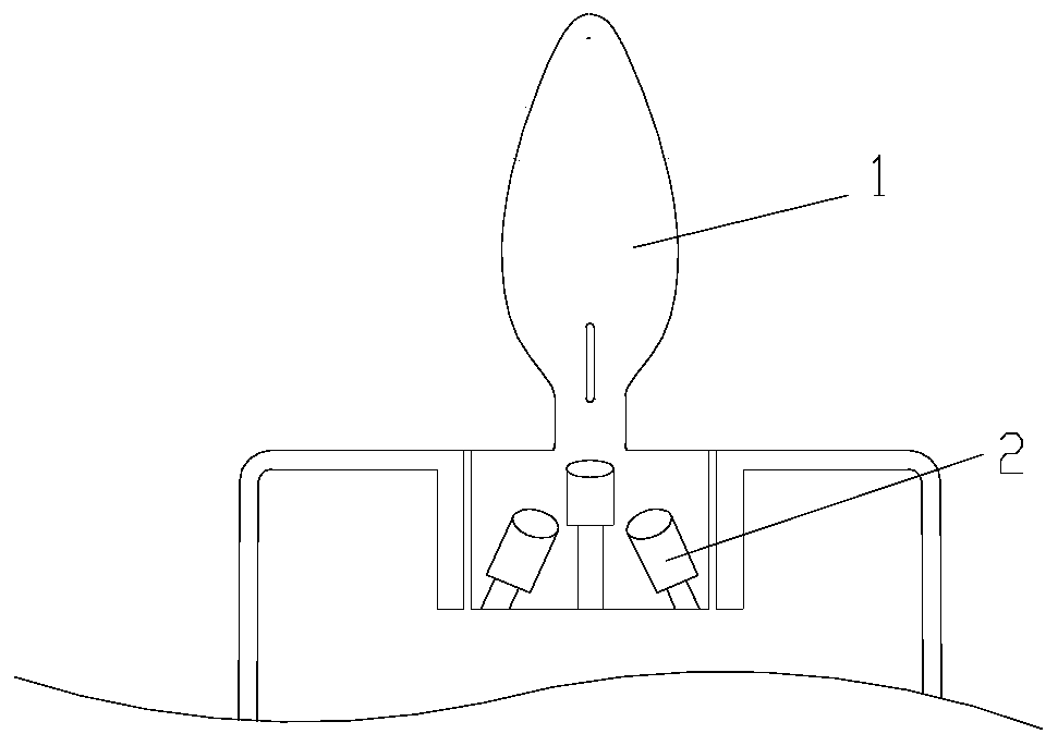
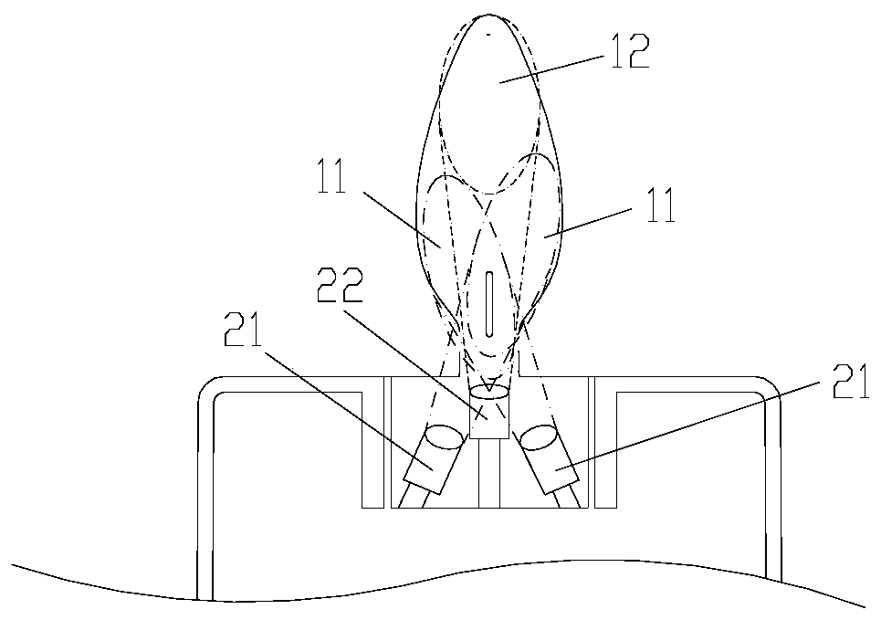
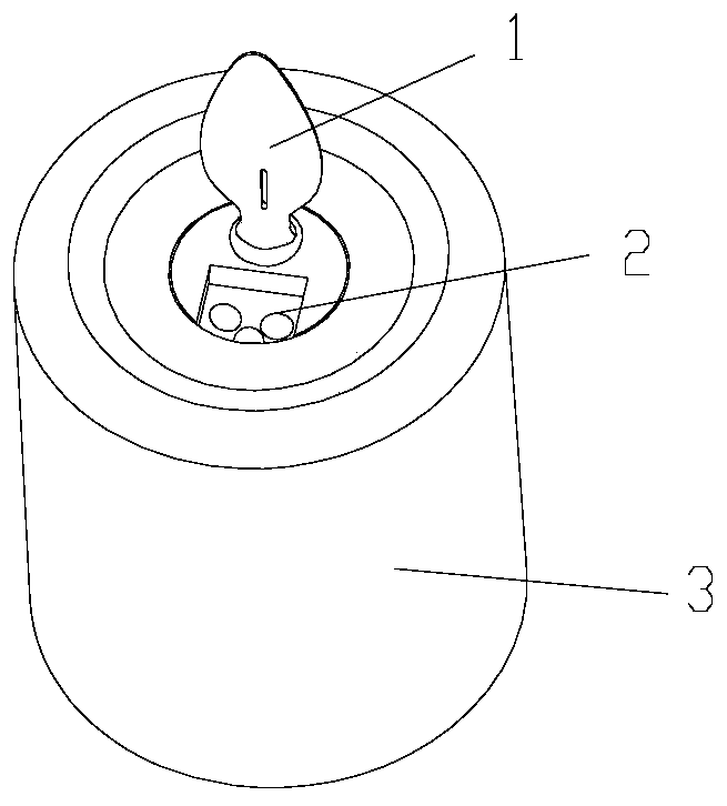
[0073] This embodiment provides a flame simulation structure, including a flame sheet 1, a control device, at least one set of inner flame light sources 21 and at least one set of outer flame light sources 22; the inner flame light sources 21 and the outer flame light sources 22 are respectively swingable and connected with The swinging mechanism 4 is arranged in a manner or in a non-swinging manner; the projection directions of the inner flame light source 21 and the outer flame light source 22 are respectively directed towards the flame sheet 1, so as to form an inner flame projection area 11 and an outer flame projection area 12 on the flame sheet 1 respectively The outer flame projection area 12 is on the edge and / or above the inner flame projection area 11; the inner flame light source 21 and the outer flame light source 22 are respectively connected to the control device for signals.

[0074] The flame simulation structure of the present invention can project a dynamic in...

Embodiment 3

[0086] The difference between the flame simulation structure of this embodiment and the second embodiment is that: Figure 7 As shown, in this embodiment, the outer flame light source 22 is a group, and in practical applications, the number of the outer flame light source 22 can also be more than two groups; the outer flame light source 22 is connected with a swing mechanism 4 to realize the reciprocation of the outer flame light source 22 Swing, so that the light and shadow projected by the outer flame will swing.

[0087] The swing mechanism 4 includes a light source seat 44 , a magnetic pendulum 41 connected to the light source seat 44 , a coil 42 opposite to the magnetic pendulum 41 , and a flexible wire 43 connected between the magnetic pendulum 41 and the coil 42 . The outer flame light source 22 is arranged on the light source seat 44; the coil 42 is connected with the control device, so that the control device controls the magnitude and direction of the current of the ...


PUM


Abstract

The invention provides a dynamic flame forming method. The dynamic flame forming method is characterized by comprising the following steps: projecting light emitted by a plurality of groups of light sources onto a flame sheet, wherein at least one group of light sources is used as an inner flame light source, and dynamic inner flame is formed through a position change and / or a light and shade alternating change of inner flame projection light and shadows formed by the inner flame light source on the flame sheet; taking at least one group of light sources of which the light emitting colors aredifferent from those of the inner flame light sources as outer flame light sources, wherein outer flame projection shadows formed by the outer flame light sources on the flame sheet are located at theedges and / or above the inner flame light sources; and forming the dynamic outer flame through the position change and / or the light and shade alternating change of the outer flame projection light andshadows. According to the method, the flame simulation fidelity can be improved, the structure can be simplified, and energy consumption can be reduced. The invention also provides a flame simulationstructure for realizing the method, and an electronic candle comprising the flame simulation structure.

Description

technical field [0001] The invention relates to the technical field of flame simulation, in particular to a dynamic flame forming method, a flame simulation structure and an electronic candle. Background technique [0002] In order to create a special atmosphere such as romance and warmth, people use candles as decorations; traditional candles achieve lighting through the flame formed by burning, but the candles wear out quickly, which is not conducive to energy saving and environmental protection, and the heat and odor generated during the burning process will also reduce the user's safety. comfort, and the candle flame may ignite surrounding items and pose a safety hazard. In order to avoid these problems, in recent years, people have used electronic candles instead of traditional candles for scene layout; the existing electronic candles project the light from the light source onto the flame sheet, and the swaying of the flame sheet causes the light and shadow to shake, th...

Claims


Application Information

Patent Timeline
Patent Type & Authority Applications(China)
IPC IPC(8): F21S10/04F21V23/00F21V14/02
CPCF21S10/04F21V14/02F21V23/003
Inventor 盛恬子
Owner FOSHAN MOGEN INTELLIGENT TECH CO LTD
Why Eureka
Try Eureka