Pump pressure tightness test assembly, broadside pipeline and installation method of broadside pipeline

An installation method and a technology of sealing components are applied in the direction of detecting the appearance of fluid at the leakage point and using liquid/vacuum degree to measure the liquid tightness, etc., which can solve the problems of long cycle, harsh construction environment, and consuming manpower and material resources, etc., to achieve The construction environment is good, the construction difficulty is reduced, and the construction efficiency is improved

Inactive Publication Date: 2020-04-14
WUCHANG SHIPBUILDING IND
View PDF10 Cites 4 Cited by
  • Summary
  • Abstract
  • Description
  • Claims
  • Application Information

AI Technical Summary

Problems solved by technology

[0004] The existing side pipeline installation method has the following defects: the pump pressure test needs to use copper pipes to pass through the steel plate with holes to pump and inflate, and a large number of auxiliary tools are needed, which consumes a lot of manpower and material resources; the test location is in the hull At the higher position of the subsection, workers need to use ladders to go up and down during construction, and the construction environment is relatively harsh; two pump pressure tests are required, one for the side valve in the workshop, and one for the installed valve at the ship subsection construction site. The side valve and the side pipe are sealed tested as a whole, and the period required for the closed test is long

Method used


Image

  • Pump pressure tightness test assembly, broadside pipeline and installation method of broadside pipeline
  • Pump pressure tightness test assembly, broadside pipeline and installation method of broadside pipeline
  • Pump pressure tightness test assembly, broadside pipeline and installation method of broadside pipeline

Examples


Embodiment Construction

[0041] The present invention will be described in further detail below in conjunction with the accompanying drawings and embodiments.

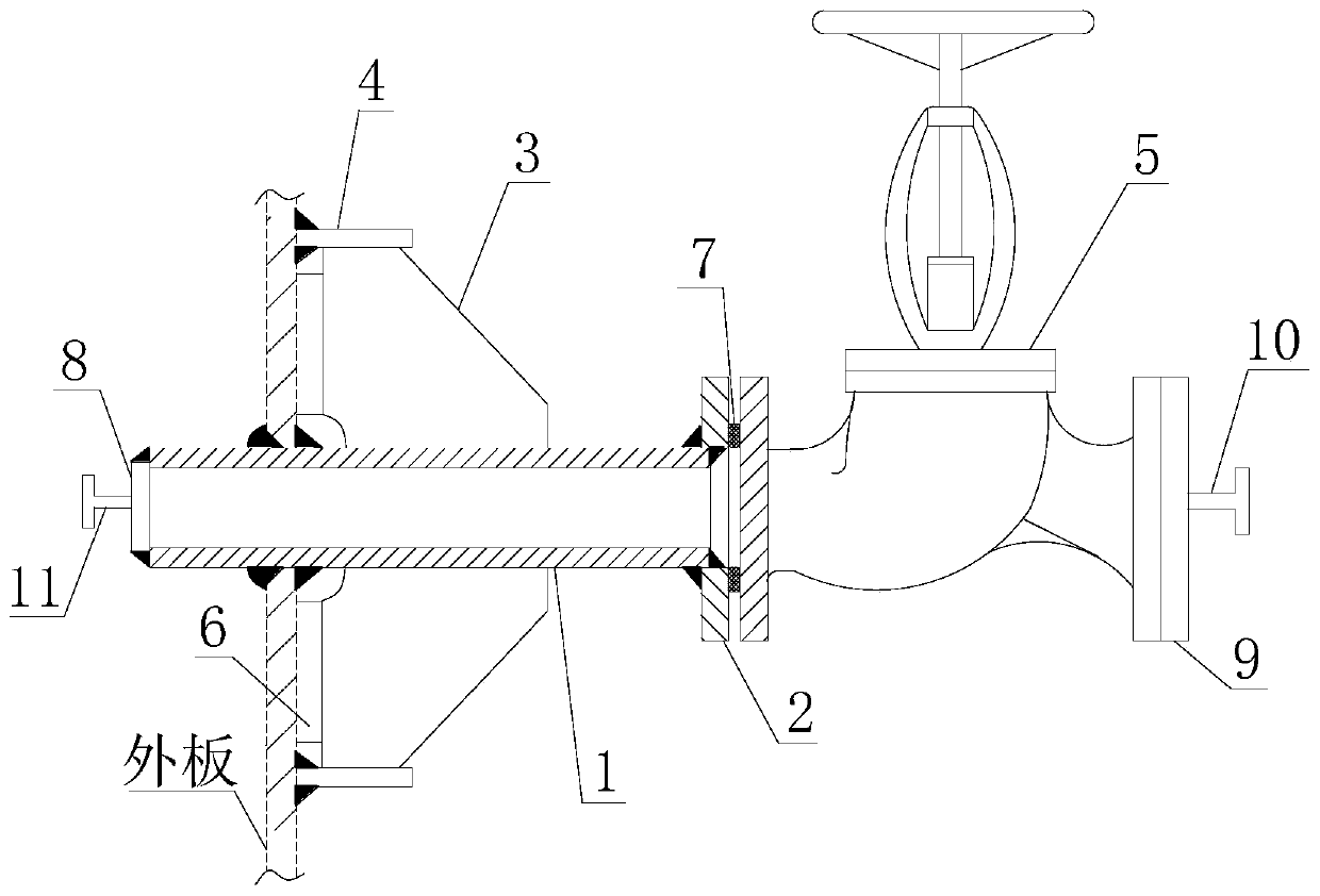
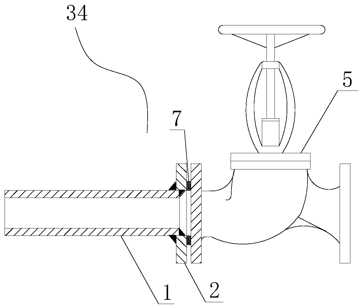
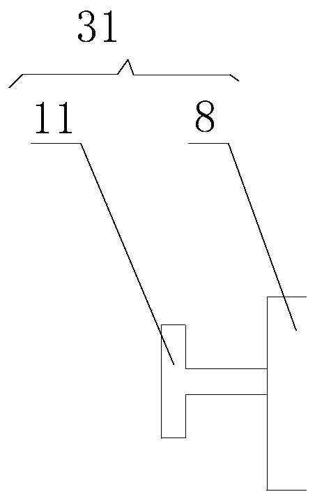
[0042] Such as figure 2 , image 3 and Figure 4 As shown, a pump pressure test assembly is used to assist in the pump pressure test of the pipe valve assembly 34 of the ship. The pipe valve assembly 34 includes the side pipe 1 and the side valve 5 . The pump pressure sealing test assembly includes a sealing test sealing plate 8 and a sealing test flange 9. The sealing test sealing plate 8 is sealingly connected to the side end surface of the side pipe 1, and a first connecting hole is opened in the center of the sealing test sealing plate 8, and a second connecting hole is set at the first connecting hole. A threaded connection pipe 11. The first threaded connecting pipe 11 directly communicates with the side pipe 1 through the first connecting hole. Preferably, the sealing plate 8 is welded to the side end surface of the side pipe 1 . ...


PUM


Abstract

The invention discloses a pump pressure tightness test assembly, a broadside pipeline and an installation method of the broadside pipeline, and relates to the field of ship installation engineering. Apipe valve assembly comprises a broadside pipe and a broadside valve, the pump pressure tightness test assembly comprises a tightness test sealing plate and a tightness test flange, the tightness test sealing plate is connected to the side end face of the broadside pipe in a sealed mode, a first connecting hole is formed in the center of the tightness test sealing plate, and a first threaded connecting pipe is arranged at the first connecting hole; the tightness test flange is detachably connected to the inlet end of the broadside valve, a second connecting hole is formed in the center of thetightness test flange, and a second threaded connecting pipe is arranged at the second connecting hole; when a pump pressure tightness test is carried out, the broadside valve is closed, a pump pressure hose is connected into the first threaded connecting pipe and the second threaded connecting pipe, and pump pressure is carried out from the two sides at the same time. According to the pump pressure tightness test assembly, the broadside pipeline and the installation method of the broadside pipeline, the pump pressure and the installation difficulty of the broadside pipeline are reduced.

Description

technical field [0001] The invention relates to the field of ship installation engineering, in particular to a pump pressure tight test assembly, a side pipeline and an installation method for the side pipeline. Background technique [0002] In order to draw seawater, use seawater to cool various equipment in the ship, and discharge the used seawater and sewage overboard, all ships need to be equipped with side piping on the shell plate. [0003] Because the side pipeline directly leads to the sea and involves ship safety, CCS (China Classification Society, Classification Society of China) has very high requirements for the test and installation quality of the side pipeline. During installation, it is necessary to perform a pump pressure test on the side valve and side pipe to ensure that after installation, the side valve, side pipe and their joints have good sealing performance. [0004] The existing side pipeline installation method has the following defects: the pump pr...

Claims


Application Information

Patent Timeline
Patent Type & Authority Applications(China)
IPC IPC(8): G01M3/04
CPCG01M3/04
Inventor 安志杰李贇胡社来
Owner WUCHANG SHIPBUILDING IND
Why Eureka
Try Eureka