Dust falling device for house building construction

A technology for dust suppression devices and houses, which is applied in the direction of spraying devices, use of liquid separation agents, and separation of dispersed particles, which can solve the problems of troublesome dust suppression work and inconvenient movement of dust suppression mechanisms, and achieve the effect of increasing the dust suppression range

Inactive Publication Date: 2020-04-17
株洲兴润高分子新材料有限公司
View PDF0 Cites 3 Cited by
  • Summary
  • Abstract
  • Description
  • Claims
  • Application Information

AI Technical Summary

Problems solved by technology

[0004] Based on the technical problems that the dust-reducing mechanism of the existing device is inconvenient to move and the dust-reducing work is troublesome, the present invention proposes a dust-reducing device for house construction

Method used


Image

  • Dust falling device for house building construction
  • Dust falling device for house building construction
  • Dust falling device for house building construction

Examples


Embodiment 1

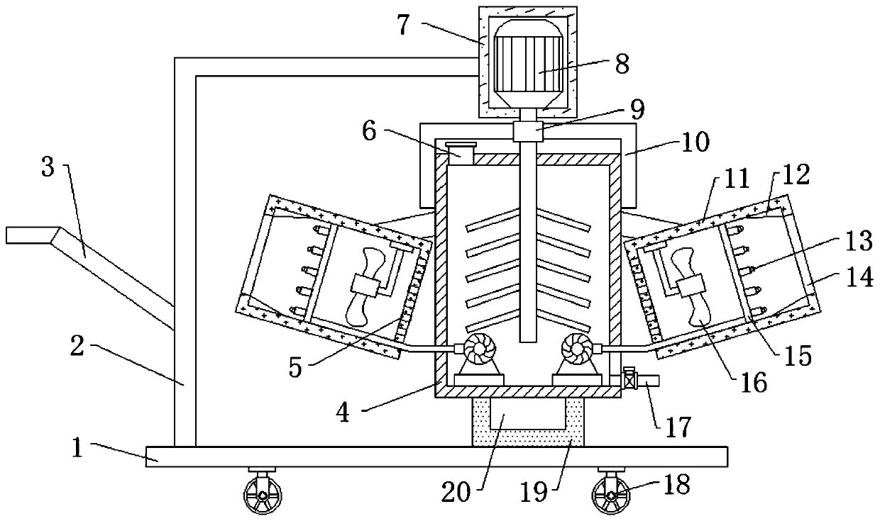
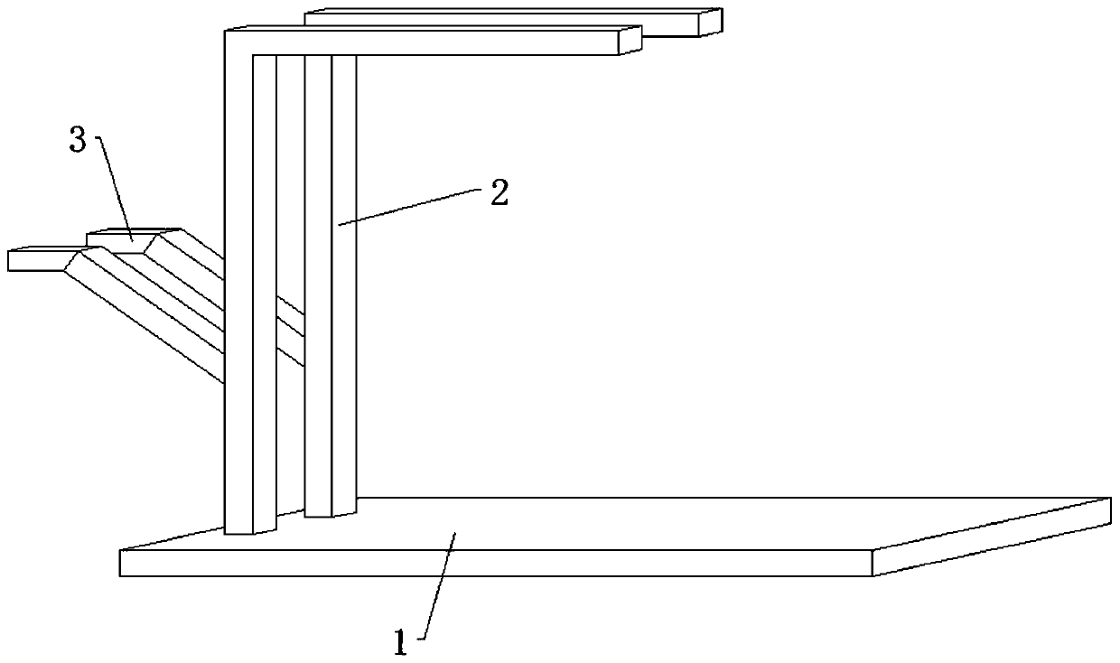
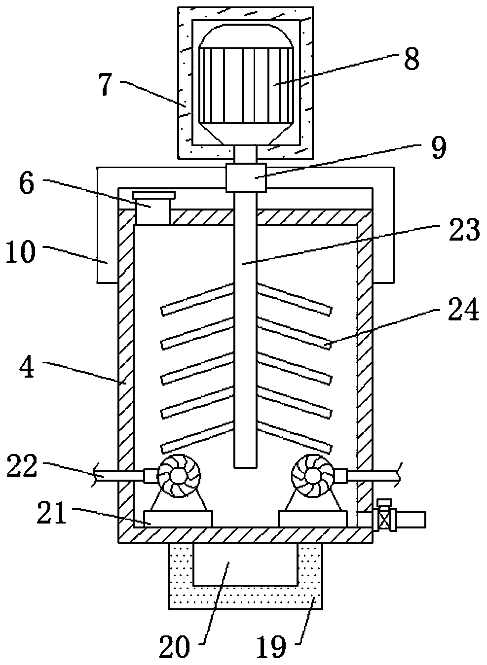
[0027] refer to Figure 1-3 , a dust suppression device for house construction, comprising a bottom plate 1 and a water tank 4, a fixing seat 19 is fixed on the top outer wall of the bottom plate 1 by bolts, a socket 20 is rotatably inserted on the top outer wall of the fixing seat 19, and the water tank 4 is fixed on the bottom wall by bolts On the top outer wall of the socket 20, two L-shaped plates 2 are fixed on one side of the top outer wall of the bottom plate 1 by bolts, one end of the L-shaped plates 2 is fixed with a handle 3 by bolts, and one end of the two L-shaped plates 2 is fixed by bolts There is the same motor box 7, and the motor box 7 is located directly above the water tank 4. The bottom inner wall of the motor box 7 is fixed with a motor 8, and one end of the output shaft of the motor 8 is keyed to a drive shaft 23, and one end of the drive shaft 23 is located at In the inside of the water tank 4, a sleeve rod 9 is sleeved on the circumference outer wall of...

Embodiment 2

[0032] refer to Figure 4 , a dust suppression device for house construction. Compared with Embodiment 1, this embodiment also includes a lighting lamp 25, and the lighting lamp 25 is fixed on one side of the outer wall of the motor box 7 by bolts.

[0033] During use, one side of the motor case 7 is provided with an illuminating lamp 25, which is convenient to provide illumination, and is convenient for the device to carry out dust reduction work when the sky is dark.


PUM


Abstract

The invention discloses a dust falling device for house building construction. The device is used for solving the problems of inconvenient movement and troublesome dust falling work of a dust fallingmechanism. The device comprises a bottom plate and a water tank, a fixing base is fixed to the outer wall of the top of the bottom plate through bolts, a socket is rotationally inserted into the outerwall of the top of the fixing base, the water tank is fixed on the top outer wall of the socket through bolts, two L-shaped plates are fixed to one side of the outer wall of the top of the bottom plate through bolts, a handle is fixed to one end of each L-shaped plate through a bolt, the same motor box is fixed to one ends of the two L-shaped plates through bolts, the motor box is located over the water tank, and a motor is fixed to the inner wall of the bottom of the motor box through bolts. Two-stage linkage is carried out through the motor, namely, a transmission shaft is driven to rotatethrough rotation of the motor, a liquid can be stirred through a stirring rod, and the whole water tank can be driven to rotate through a sleeve rod and a clamping rod, so water bodies can be evenly mixed, and all-directional dust falling can be carried out.

Description

technical field [0001] The invention relates to the technical field of dust suppression devices, in particular to a dust suppression device for building construction. Background technique [0002] Housing construction refers to the construction of houses and other buildings on land that has completed infrastructure construction, including residential buildings, industrial plants, commercial buildings, office buildings, and other special-purpose buildings. Although the infrastructure construction has been completed, the construction site A large amount of dust will still be generated, so it is necessary to use a dust suppression device for house construction to suppress dust. [0003] Most of the existing dust-reducing devices have the following disadvantages: inconvenient movement, the dust-reducing device can only work in one direction, and the dust-reducing work is troublesome, and the existing devices are not easy to solve such problems. Therefore, there is an urgent need...

Claims


Application Information

Patent Timeline
Patent Type & Authority Applications(China)
IPC IPC(8): B01D47/06B01D47/16B05B15/25
CPCB01D47/06B01D47/16B05B15/25
Inventor 宋杰刘旭东
Owner 株洲兴润高分子新材料有限公司
Why Eureka
Try Eureka