
Connecting structure for gun barrel and pedestal of fog gun machine

A technology for connecting structures and cannons, applied in the direction of dispersed particle separation, injection devices, chemical instruments and methods, to achieve the effect of slowing down the impact of vibration and ensuring the stability of lateral support

Active Publication Date: 2020-04-17
濉溪初新工业设计有限公司
View PDF13 Cites 0 Cited by
  • Summary
  • Abstract
  • Description
  • Claims
  • Application Information

AI Technical Summary

Problems solved by technology

[0004] Aiming at the shortcomings of the connection method between the upper barrel and the lower base of the existing fog cannon proposed in the background technology, the present invention provides a connection structure between the barrel and the base of the fog cannon, which has the functions of preventing wire winding, The advantage of the 360-degree rotation of the gun barrel parts solves the problems raised in the above-mentioned background technology

Method used


Image

  • Connecting structure for gun barrel and pedestal of fog gun machine
  • Connecting structure for gun barrel and pedestal of fog gun machine
  • Connecting structure for gun barrel and pedestal of fog gun machine

Examples


Embodiment Construction

[0016] The following will clearly and completely describe the technical solutions in the embodiments of the present invention with reference to the accompanying drawings in the embodiments of the present invention. Obviously, the described embodiments are only some, not all, embodiments of the present invention. Based on the embodiments of the present invention, all other embodiments obtained by persons of ordinary skill in the art without making creative efforts belong to the protection scope of the present invention.

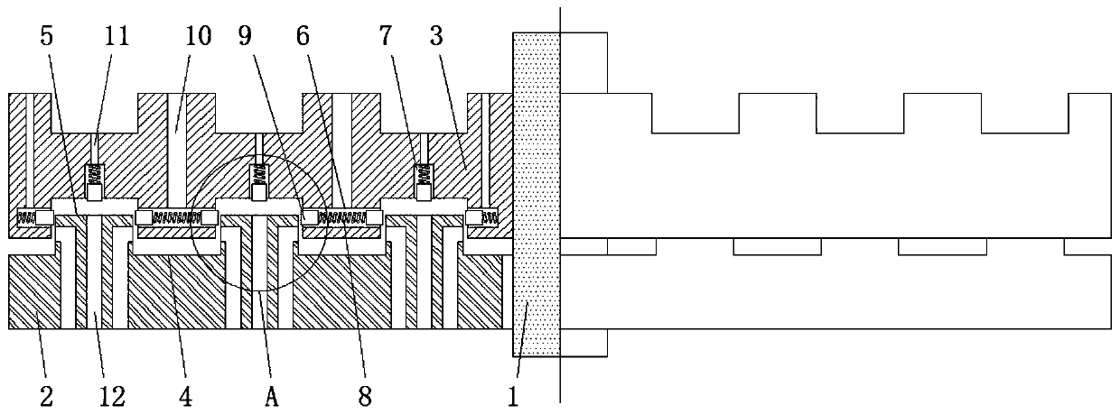
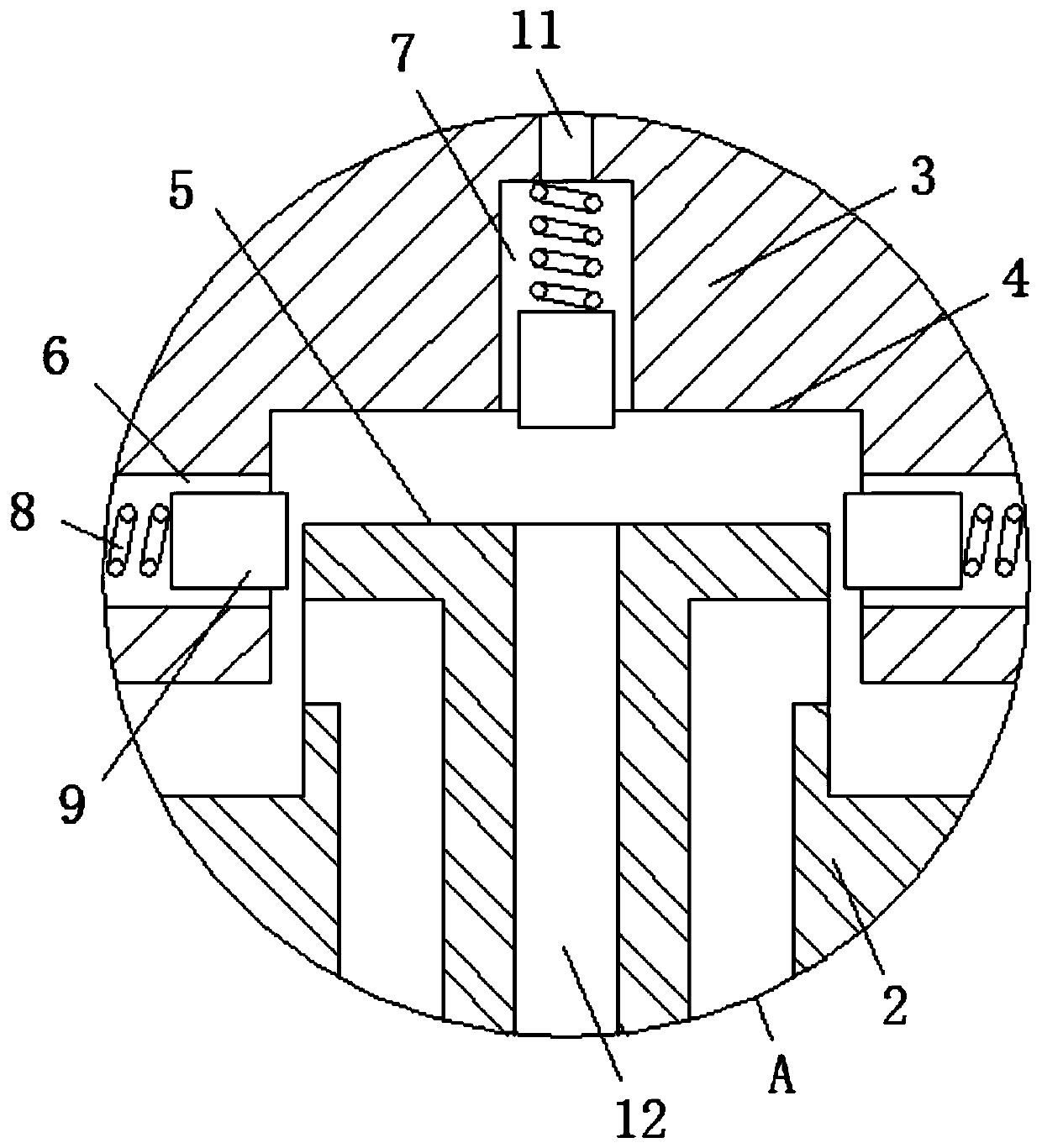
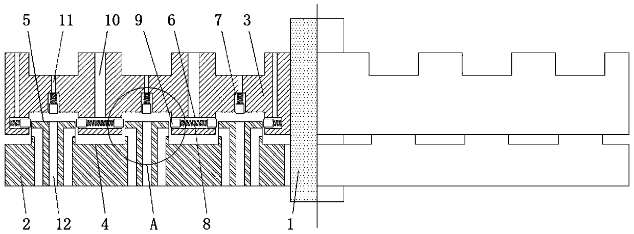
[0017] see Figure 1-2 , a connection structure between the barrel of the fog cannon machine and the base, including a supporting shaft 1, the outer part of the supporting shaft 1 is fixedly sleeved with a swivel bearing 3, and the outer part of the supporting shaft 1 is movably sleeved under the swivel bearing 3 The positioning platform 2, the upper part of the rotating platform 3 is used to fix the upper part of the fog gun machine, the positioning platform ...


PUM


Abstract

The invention relates to the technical field of fog gun machines, and discloses a connecting structure for a gun barrel and a pedestal of a fog gun machine. The connecting structure comprises a supporting rotary shaft, wherein the supporting rotary shaft is fixedly sleeved with a rotary bearing platform; the supporting rotary shaft is movably sleeved with a positioning bearing platform at a position below the rotary bearing platform; annular clamping grooves are formed in the top end of the positioning bearing platform, annular bosses are arranged at the top end of the positioning bearing platform, the annular clamping grooves and the annular bosses are distributed alternately; and annular clamping grooves are formed in the bottom part of the rotary bearing platform, and annular bosses arearranged at the bottom part of the rotary bearing platform. Through arranging the positioning bearing platform and the rotary bearing platform, an upper electric appliance control line is terminatedto a sliding contact block on the rotary bearing platform, a lower electric appliance control line is terminated to a fixed sliding ring on the positioning bearing platform, and the sliding contact block and the fixed sliding ring are in sliding contact electric connection of the contact and the sliding ring, thus an upper electric appliance and a lower electric appliance can be rotated respectively, the wire winding influence of a power control line is avoided, and the 360-degree rotating operation of the upper electric appliance is completely realized.

Description

technical field [0001] The invention relates to the technical field of fog cannons, in particular to a connection structure between a barrel of a fog cannon and a base. Background technique [0002] The fog cannon machine is mainly used for dust control, moisturizing and cooling, spraying and disease prevention, etc. It is aimed at the dust suppression of urban streets, construction sites, open material storage yards, mining and other high dust site environments. After the high-pressure water is atomized through the atomizing nozzle, it is blown to the environment by the axial flow fan, which has the characteristics of long range and high coverage. [0003] The upper gun barrel and the lower base are connected by a horizontal rotating support, so that the gun barrel can be rotated. However, due to the limitation of the wire connection of the lower control electronics, the 360-degree rotation of the gun barrel is restricted, making it difficult to realize the actual use of th...

Claims


Application Information

Patent Timeline
Patent Type & Authority Applications(China)
IPC IPC(8): B05B13/04B05B15/00B01D47/08
CPCB01D47/08B05B13/0421B05B15/00
Inventor 黄亮亮
Owner 濉溪初新工业设计有限公司
Learn More