
Double-station automatic short pipe bending equipment

A dual-station, short-tube technology, applied in metal processing equipment, positioning devices, manufacturing tools, etc., can solve the problems of heavy equipment, low pipe bending efficiency, waste of manpower and time, saving labor and time, and improving efficiency. and high-quality, highly automated effects

Active Publication Date: 2020-04-17
新乡创想自动化科技有限公司
View PDF10 Cites 1 Cited by
  • Summary
  • Abstract
  • Description
  • Claims
  • Application Information

AI Technical Summary

Problems solved by technology

[0002] The function of the pipe bender is to bend the vertical pipe into a U shape or other bending shapes. The pipe bender is mainly used for bending steel pipes such as electric power construction, boilers, bridges, ships, and decorations. It has multiple functions. , reasonable structure, simple operation and other advantages, the current types of pipe benders are diverse, including short pipe benders and long pipe benders, long pipe benders are equipment that is used more, and short pipe benders are more Few, most of them are long pipe benders that can also be used for short pipe bends after adjustment, but such equipment is not completely suitable for bending short pipes, and some equipment is relatively cumbersome, requiring repeated manual adjustments, wasting manpower and time ; Moreover, some pipe benders can only bend one pipe at a time, and the pipe bending efficiency is low

Method used


Image

  • Double-station automatic short pipe bending equipment
  • Double-station automatic short pipe bending equipment
  • Double-station automatic short pipe bending equipment

Examples


Embodiment Construction

[0025] In order to facilitate the understanding of the present invention, the present invention will be described in more detail below with reference to the drawings and specific embodiments. The drawings show preferred embodiments of the present invention. However, the present invention can be implemented in many different forms and is not limited to the embodiments described in this specification. On the contrary, the purpose of providing these embodiments is to make the understanding of the disclosure of the present invention more thorough and comprehensive.

[0026] It should be noted that when an element is referred to as being "fixed to" another element, it can be directly on the other element or a central element may also exist. When an element is considered to be "connected" to another element, it can be directly connected to the other element or an intermediate element may be present at the same time. The terms "fixed", "integrated", "left", "right" and similar express...


PUM


Abstract

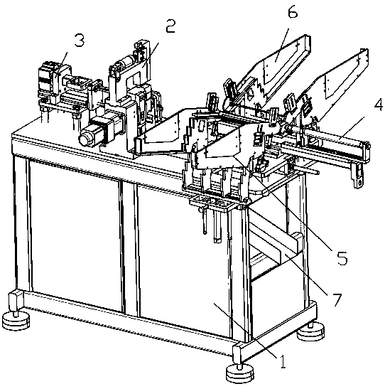
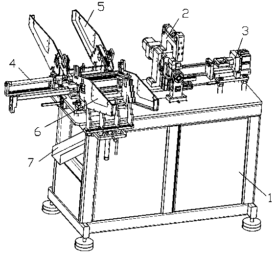
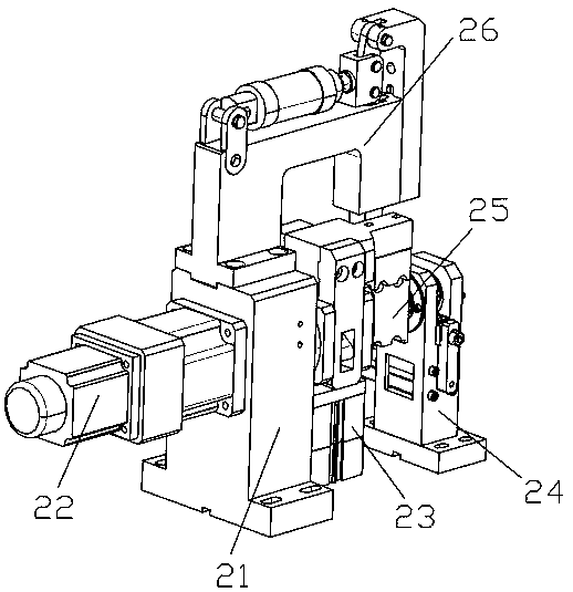
The invention relates to double-station automatic short pipe bending equipment. The pipe bending equipment comprises a workbench, a short pipe bending mechanism is arranged in the middle of the uppersurface of the workbench, an anti-stretching device for assisting short pipe bending is arranged on the left side of the short pipe bending mechanism, a square through hole is formed in the position,corresponding to the working end of the short pipe bending mechanism, of the upper surface of the workbench, a discharging sliding groove is formed below the square through hole, the upper end of thedischarging sliding groove is fixedly connected with the lower surface of the table top of the workbench, a short pipe feeding device is arranged on the right side of the short pipe bending mechanism,a first short pipe feeding device and a second short pipe feeding device are arranged on the front side and the rear side of the short pipe feeding device correspondingly, the first short pipe feeding device and the second short pipe feeding device are oppositely arranged, and discharging openings of the first short pipe feeding device and the second short pipe feeding device are connected with the working end of the short pipe feeding device. The pipe bending equipment is high in automation degree, the labor cost is saved, the pipe bending efficiency and quality are improved, and the good market application value is achieved.

Description

Technical field [0001] The invention relates to the technical field of automatic short tube bending, in particular to a double-station short tube automatic bending equipment. Background technique [0002] The function of the pipe bender is to bend the vertical pipe into a U-shape or other bending shape. The pipe bender is mainly used for bending steel pipes such as electric power construction, boilers, bridges, pipe benders, ships, and decoration. It has multiple functions , Reasonable structure, simple operation, etc. Now there are various types of pipe benders, including short pipe benders and long pipe benders. Long pipe benders are more commonly used equipment, and short pipe benders Less, most of them are long-tube benders that can also be used for short-tube bending after adjustment, but such equipment is not completely suitable for short-tube bending, and some equipment is relatively heavy and requires repeated manual adjustments, which wastes manpower and time ; And some...

Claims


Application Information

Patent Timeline
Patent Type & Authority Applications(China)
IPC IPC(8): B21D7/00B21D43/00B21D43/04
CPCB21D7/00B21D43/003B21D43/04
Inventor 罗方芦张鸿涛
Owner 新乡创想自动化科技有限公司
Learn More