Profile automatic bending device, method and application of using it to realize three-dimensional bending

A bending device and profile technology, which is applied to the feeding device, positioning device, storage device, etc., can solve the problems of long bending time, early fatigue life of fixed parts, and low bending accuracy, and achieve consistent deformation effect and deformation accuracy. High, high bending efficiency

Active Publication Date: 2021-08-17
CIXI INST OF BIOMEDICAL ENG NINGBO INST OF MATERIALS TECH & ENG CHINESE ACAD OF SCI +2
View PDF0 Cites 0 Cited by
  • Summary
  • Abstract
  • Description
  • Claims
  • Application Information

AI Technical Summary

Problems solved by technology

[0008] (1) It is necessary to make a three-dimensional physical model of the patient's bone. The current process method takes more than 10 hours to make the model, which increases the patient's waiting time for surgery, and the production cost is high;
[0009] (2) Manually bending the frame material based on the doctor's experience, the bending accuracy is low, and the bending time is long; even for the same patient, different doctors cannot guarantee the consistency of the fixing parts when bending manually;
[0010] (3) Due to the complex shape of the bones, when manual bending is used, due to the large number of repeated adjustments, it is easy to cause early fatigue and insufficient life of the skeleton material fixtures such as titanium alloys.
[0011] (4) Manual bending with simple tools can only ensure a good fit between the fixation piece and the patient's bone at local points, but cannot guarantee the best spatial fit at all coordinate points, so it is comfortable for the patient to use Both the degree and the service life of the fixing parts have a certain degree of influence

Method used


Image

  • Profile automatic bending device, method and application of using it to realize three-dimensional bending
  • Profile automatic bending device, method and application of using it to realize three-dimensional bending
  • Profile automatic bending device, method and application of using it to realize three-dimensional bending

Examples


Embodiment 1

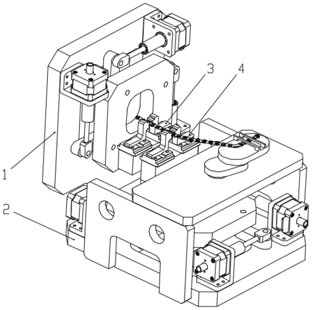
[0042] In this embodiment, the profile automatic bending device such as figure 1 As shown, a first motion mechanism 1 and a second motion mechanism 2 are included.

[0043] Such as figure 2 As shown, the first clamping mechanism 3 is provided on the first moving mechanism 1 .

[0044] Such as image 3 As shown, the second moving mechanism 2 is provided with a first clamping mechanism 4 .

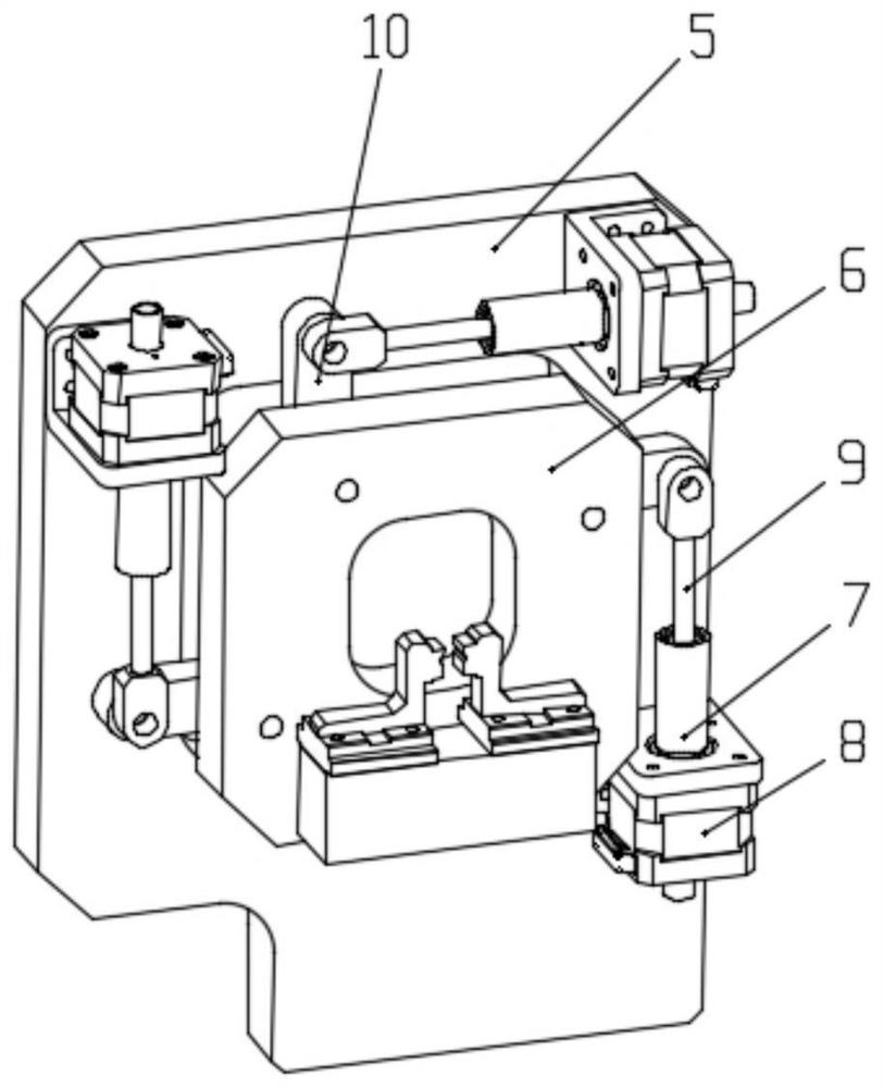
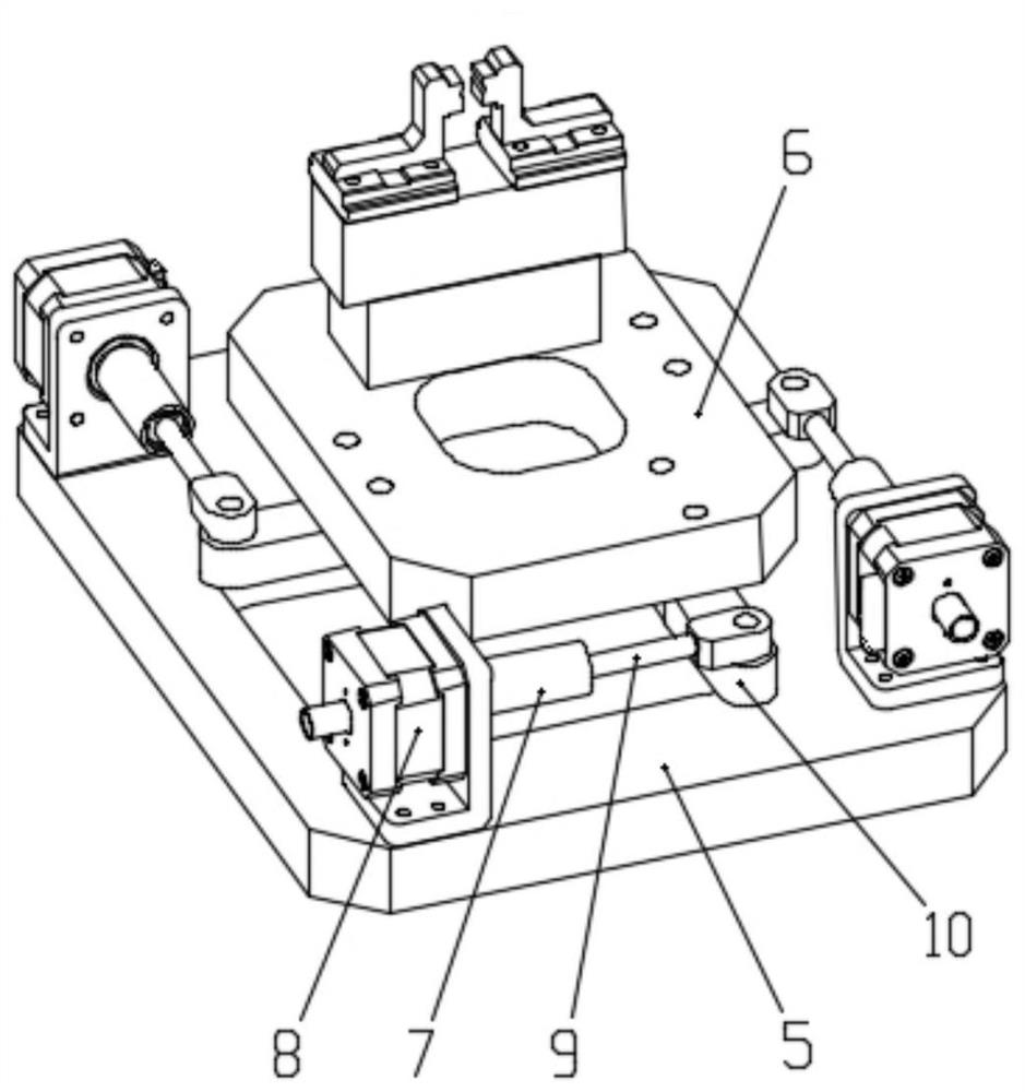
[0045] Such as figure 2 , 3 As shown, the mechanism of the first motion mechanism 1 and the second motion mechanism 2 are exactly the same, both are 3-PRR parallel motion mechanisms, driven by a closed stepping screw motor, which can drive to realize two-dimensional motion and rotation in the plane sports.

[0046] Such as figure 2 As shown, the 3-PRR parallel kinematic mechanism includes a base, a moving platform 6 on the base 5 and three transmission mechanisms 7 . Each transmission mechanism includes a closed-type stepping screw motor 8, a P-width driving element 9, a connectin...

Embodiment 2

[0056] In this embodiment, the profile automatic bending device is exactly the same as that in Embodiment 1.

[0057] The automatic deformation device is used for the repair of the patient's jawbone. The modification method is: according to the 3D model of the patient's jawbone, the titanium alloy material is bent through the device to match the 3D model of the patient's jawbone. The bone model is consistent.

[0058] The method of bending titanium alloy material with this device is as follows:

[0059] (1) At the initial position, the first clamping machine and the second clamping mechanism fix different positions of the titanium alloy plate through the clamping part, that is, the first clamping mechanism clamps the A position of the titanium alloy plate, and the second clamping mechanism The mechanism clamps the B position of the titanium alloy plate;

[0060] (2) Carry out the following process a, process b, or process a and process b, so that the position A and position ...

Embodiment 3

[0067] In this embodiment, the profile automatic bending device is basically the same as in Embodiment 1, the difference is that in this embodiment, such as Figure 4 As shown, the profile automatic bending device also includes an auxiliary feeding mechanism, including a base 11, a first connecting rod 12, a second connecting rod 13 and a rotary motion pair 14, and the rotary motion pair 14 is connected to the base 11 through the first connecting rod 12. On, the second connecting rod 13 is fixed on the rotary kinematic pair 14. In the working state, the displacement of the unclamped part of the material in the plane is adjusted by the rotary motion pair, so that the position of the unclamped part is kept in a direction that is conducive to the feeding of the clamped part.


PUM


Abstract

The invention provides an automatic profile bending device, a method for realizing three-dimensional bending by using the device, and an application thereof. Two motion mechanisms that can drive two-dimensional translational motion and rotation motion in the plane are adopted, and the two motion mechanisms form a certain angle, combined with the different positions of the materials clamped by the two clamping mechanisms, it is realized under the drive of the two motion mechanisms The relative deformation movement of the clamped position realizes the required three-dimensional bending of the material by changing the clamping position. It has the advantages of high deformation efficiency, high deformation accuracy, repeatable operation and consistent deformation effect. It can be applied to medical bone repair and other technologies field.

Description

technical field [0001] The invention belongs to the technical field of profile processing and deformation treatment, and in particular relates to an automatic profile bending device, a method for realizing three-dimensional bending by using the same, and an application thereof. Background technique [0002] The processing and deformation treatment of profiles is applied in many fields of modern society. [0003] For example, in view of the damage or loss of bones such as the facial and jaw bones of patients caused by various diseases or accidents, the existing main medical method is to use titanium alloy or other biocompatible materials as the skeleton material to strengthen and splice the bone segments, according to Based on the three-dimensional shape data of the patient's face, the skeleton material is bent into a skeleton structure that matches the three-dimensional shape of the patient's face, and then the skeleton structure is fixed to the undamaged bone of the patient...

Claims


Application Information

Patent Timeline
Patent Type & Authority Patents(China)
IPC IPC(8): B21D11/22B21D11/00B21D11/14B21D43/00
CPCB21D11/00B21D11/14B21D11/22B21D43/003
Inventor 伏荣真左国坤蒋灿华张佳楫梁烨宋涛史斌君
Owner CIXI INST OF BIOMEDICAL ENG NINGBO INST OF MATERIALS TECH & ENG CHINESE ACAD OF SCI
Why Eureka
Try Eureka