Automatic welding device

A technology of automatic welding and welding parts, applied in the direction of welding accessories, etc., can solve the problems of automatic feeding of valve joints, high scrap rate, low welding efficiency, etc., and achieve the effect of ensuring welding accuracy, avoiding human errors, and improving product qualification rate

Pending Publication Date: 2020-04-17
NINGBO XINZHOU RESISTANCE WELDER
View PDF0 Cites 2 Cited by
  • Summary
  • Abstract
  • Description
  • Claims
  • Application Information

AI Technical Summary

Problems solved by technology

In practical applications, although the shape and structure of the tubular connector 100.1 are consistent, the shapes of the valve block 100.2 are various and not the only shape, so it is difficult to separate the valve connector 100 and the valve core 101 by means of a vibrating disc. Carry out automatic feeding, because conveying...

Method used


Image

  • Automatic welding device
  • Automatic welding device
  • Automatic welding device

Examples


Embodiment Construction

[0033] The present invention will be further described below in conjunction with the accompanying drawings and specific embodiments.

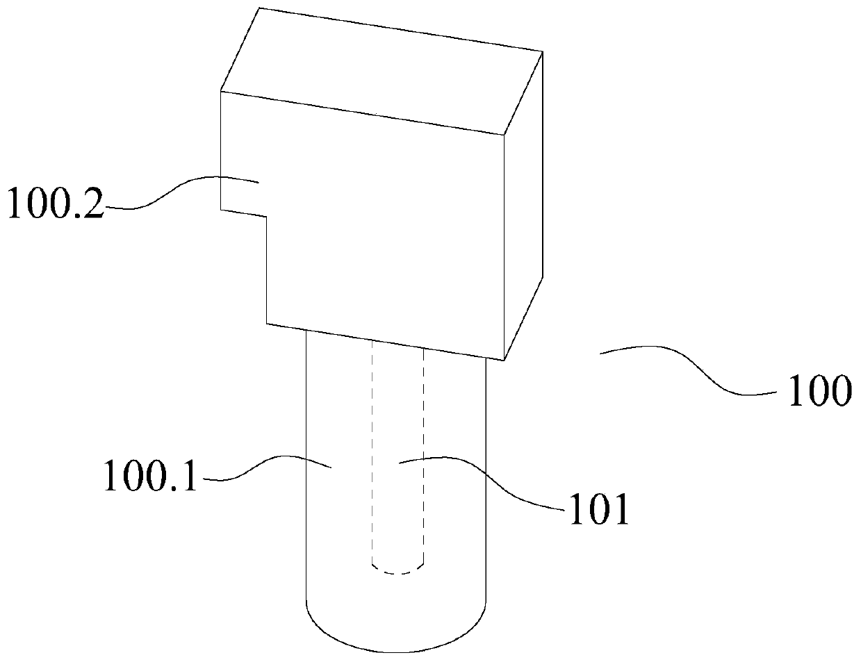
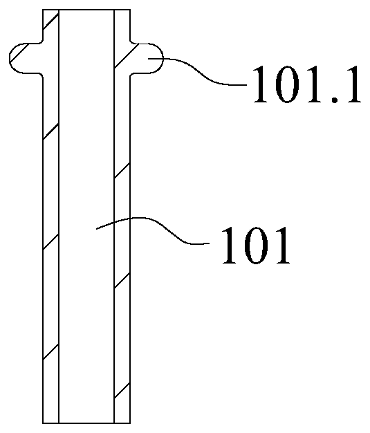
[0034] In the description of the present invention, it should be noted that the orientation or positional relationship indicated by the terms "directly above", "up and down", "upper end", "lower end" and "outer edge" are based on the orientation or positional relationship shown in the drawings. The positional relationship is only for the convenience of describing the present invention and simplifying the description, but does not indicate or imply that the referred device or element must have a specific orientation, be constructed and operated in a specific orientation, and thus should not be construed as limiting the present invention. In addition, the terms "first" and "second" are only used for descriptive purposes, for distinguishing from each other, and should not be understood as indicating or implying relative importance.

[0035] In the...


PUM


Abstract

The invention discloses an automatic welding device which comprises a rack, the rack is provided with a welding mechanism, the welding mechanism comprises an upper welding head tool and a lower welding head tool, the upper welding head tool is provided with an upper welding head, the lower welding head tool is provided with a lower welding head, and the upper welding head and the lower welding head are connected to the positive electrode and the negative electrode of a weldment transformer respectively; the workpiece feeding mechanism is used for conveying the workpieces to be welded to the position under the upper welding head one by one; the weldment feeding mechanism is used for conveying weldments to be positioned above the lower welding head one by one; the driving mechanism is used for driving the lower welding head to move towards the upper welding head until the welding piece is in contact conduction with the workpiece to generate a welding arc so as to realize welding fixation; and the controller is electrically connected with the welding mechanism, the workpiece feeding mechanism, the weldment feeding mechanism and the driving mechanism, and automatic control over the welding process is achieved. The welding device is high in welding precision, high in efficiency and low in cost.

Description

technical field [0001] The invention relates to the technical field of welding equipment, in particular to an automatic welding device. Background technique [0002] like figure 1 As shown, it is a valve connector 100 in the prior art, which includes a tubular connector 100.1 and a valve block 100.2. A valve core 101 is provided at the bottom of the inner cavity of the tubular connector 100.1. Since the outer diameter of the valve core 101 is small, And it itself is also a tubular body with a through hole, which is difficult and costly to process at one time. Therefore, in the actual production process, the valve core 101 is usually connected to the bottom of the inner cavity of the tubular connector 100.1 by welding in the later stage. , forming a complete valve joint 100 . In practical applications, although the shape and structure of the tubular connector 100.1 are consistent, the shapes of the valve block 100.2 are various and not the only shape, so it is difficult to ...

Claims


Application Information

Patent Timeline
IPC IPC(8): B23K9/32
CPCB23K9/32
Inventor 陈增光
Owner NINGBO XINZHOU RESISTANCE WELDER
Why Eureka
Try Eureka