
Reversing mechanism for electronic switch

An electronic switch and reversing mechanism technology, applied in the directions of manipulators, chucks, workpiece clamping devices, etc., can solve the problems of motor impact, slow reversing speed of reversing mechanism, and inaccurate flip angles, etc. high precision

Inactive Publication Date: 2020-04-17
重庆秉为科技有限公司
View PDF5 Cites 0 Cited by
  • Summary
  • Abstract
  • Description
  • Claims
  • Application Information

AI Technical Summary

Problems solved by technology

The existing reversing mechanism usually flips the fixture directly through the motor, so that the electronic switch is flipped along with the fixture. Since the reversing mechanism is used frequently, after long-term use, there may be a certain error in the rotation angle of the motor, resulting in an inaccurate flip angle. In addition, in order to prevent the motor from receiving excessive impact during the forward and reverse rotation process, and to prevent the excessive moment of inertia from affecting the reversing accuracy, the reversing speed of the existing reversing mechanism is relatively slow.

Method used


Image

  • Reversing mechanism for electronic switch
  • Reversing mechanism for electronic switch

Examples


Embodiment Construction

[0034] In the following description, numerous specific details are given in order to provide a more thorough understanding of the present invention. It will be apparent, however, to one skilled in the art that the present invention may be practiced without one or more of these details. In other examples, some technical features known in the art are not described in order to avoid confusion with the present invention.

[0035] It should be understood that the invention can be embodied in different forms and should not be construed as limited to the embodiments set forth herein. Rather, these embodiments are provided so that this disclosure will be thorough and complete, and will fully convey the scope of the invention to those skilled in the art. In the drawings, like reference numerals refer to like components throughout.

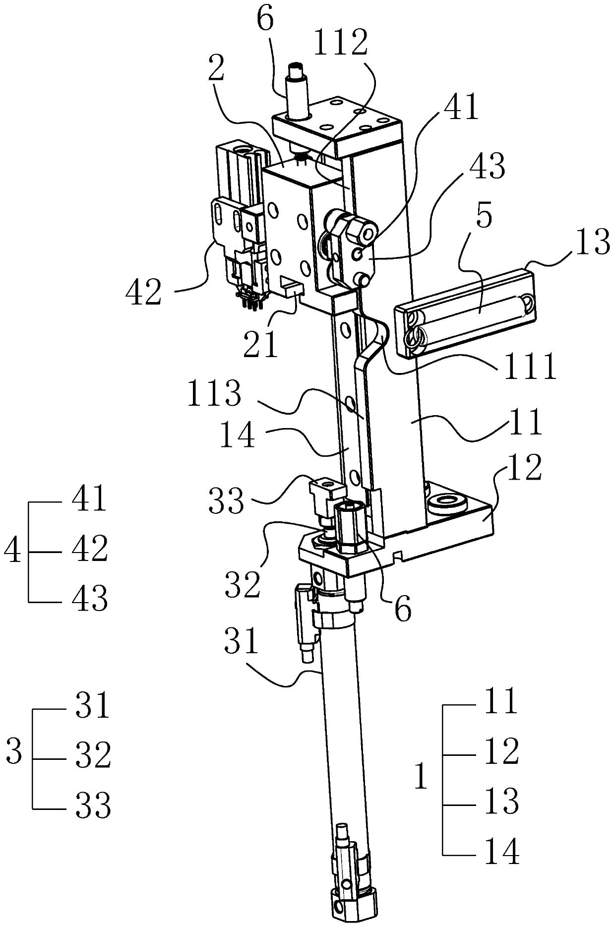
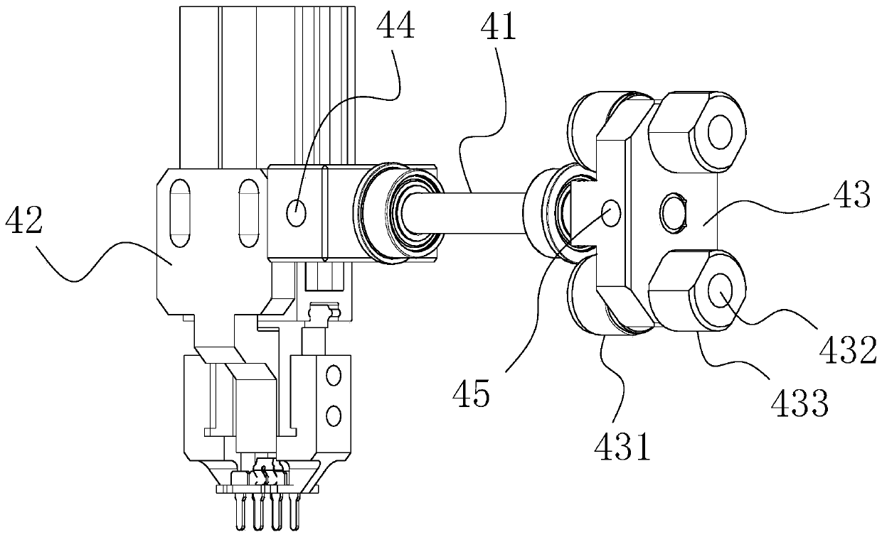
[0036] see in conjunction figure 1 , figure 2 , the reversing mechanism for electronic switch of the present invention comprises:

[0037] A base 1, ...


PUM


Abstract

The invention discloses a reversing mechanism for an electronic switch, which comprises a base, a sliding seat, an air cylinder, an overturning assembly and a tension spring, wherein a guide notch isformed in the base, the sliding seat is arranged on the base in a sliding mode, and the air cylinder is used for driving the sliding seat to slide on the base in a reciprocating mode; the overturningassembly comprises a rotating shaft, a clamp and a follow-up overturning block, the rotating shaft is rotatably mounted on the sliding seat, and an overturning guide part is arranged on the follow-upoverturning block; the tension spring is pulled between the base and the follow-up overturning block; the mounting position of the tension spring on the follow-up overturning block deviates from the axis of the rotating shaft; the guide notch is formed corresponding to the center position of the path of the overturning guide part, and the tension spring is arranged corresponding to the center position of the stroke of the sliding base, so that when the air cylinder drives the sliding seat to slide, the overturning guide part is pulled into the guide notch by the tension spring and then broughtout of the guide notch by the sliding seat to drive the overturning assembly to rotate. In the reversing mechanism, the overturning angle is constant, the reversing precision is high, and rapid overturning of the electronic switch can be achieved.

Description

technical field [0001] The invention belongs to processing tooling for electronic components, in particular to a reversing mechanism for electronic switches. Background technique [0002] In the production process of electronic switches, the production line is usually used to process in sequence. Among the various processes, some processes process the front of the electronic switch, and some processes process the back of the electronic switch. Therefore, it is often necessary to positively process the electronic switch. The opposite side is reversed for processing. The existing reversing mechanism usually flips the fixture directly through the motor, so that the electronic switch is flipped along with the fixture. Since the reversing mechanism is used frequently, after long-term use, there may be a certain error in the rotation angle of the motor, resulting in an inaccurate flip angle. In addition, in order to prevent the motor from receiving an excessive impact during the ...

Claims


Application Information

Patent Timeline
Patent Type & Authority Applications(China)
IPC IPC(8): B25B11/00B25J15/00
CPCB25B11/00B25J15/00
Inventor 程先金刘钟
Owner 重庆秉为科技有限公司
Learn More