Supercharge Your Innovation With Domain-Expert AI Agents!

Pushing and pressing vegetable cutter

A vegetable cutting machine and push plate technology, which is applied in metal processing, food processing, applications, etc., can solve the problems of large device volume, high cost, inconvenient use of food cutting devices, etc., and achieve the effect of small size and low device cost

Pending Publication Date: 2020-04-17
GUANGZHOU FUGANG WANJIA INTELLIGENT TECH CO LTD
View PDF0 Cites 0 Cited by
  • Summary
  • Abstract
  • Description
  • Claims
  • Application Information

AI Technical Summary

Problems solved by technology

At present, common food cutting devices can be roughly divided into two types. One is to install the knife holder on the knife holder, place the food material on the knife, and push the food material to the knife to make the food material pass through the knife to achieve cutting. , when the food material cutting device needs to cut the food material into a specified shape, the specified knife needs to be installed on the knife holder in advance. If the food material needs to be cut into other shapes, the knife needs to be replaced, which leads to the use of Inconvenient, when cutting the ingredients into segments, it is necessary to install a cutting knife on the knife holder, and when cutting the ingredients into slices, it is necessary to replace the knife so that the cutting knife can be installed on the knife holder
In order to overcome the problem of changing knives during use, there is another food cutting device in the prior art. This device allows users to choose knives and does not need to change knives by setting multiple sets of knives and multiple push plates. The shortcomings of this device are also very obvious. Since multiple sets of knives need to be set up for users to choose to use, it is necessary to set a corresponding push plate and vegetable outlet for each set of knives. Multiple sets of push plates will lead to higher device costs. The mouth of the dish also leads to a larger device volume

Method used


Image

  • Pushing and pressing vegetable cutter
  • Pushing and pressing vegetable cutter
  • Pushing and pressing vegetable cutter

Examples


Embodiment Construction

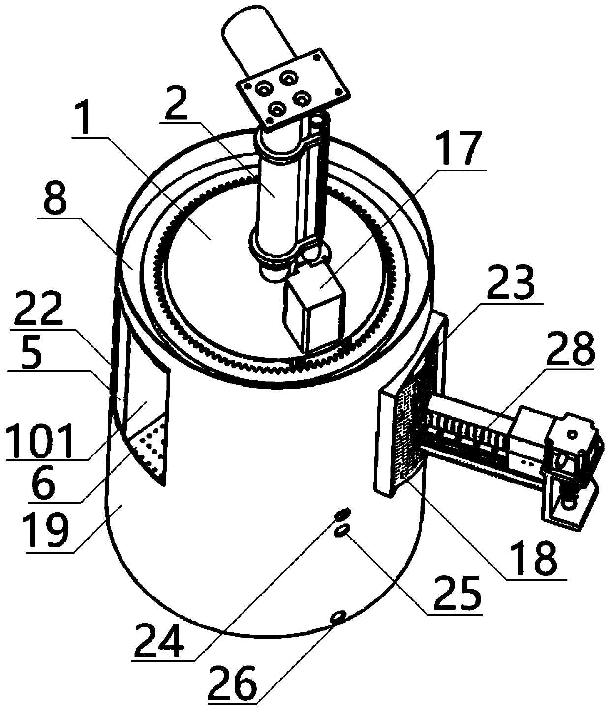
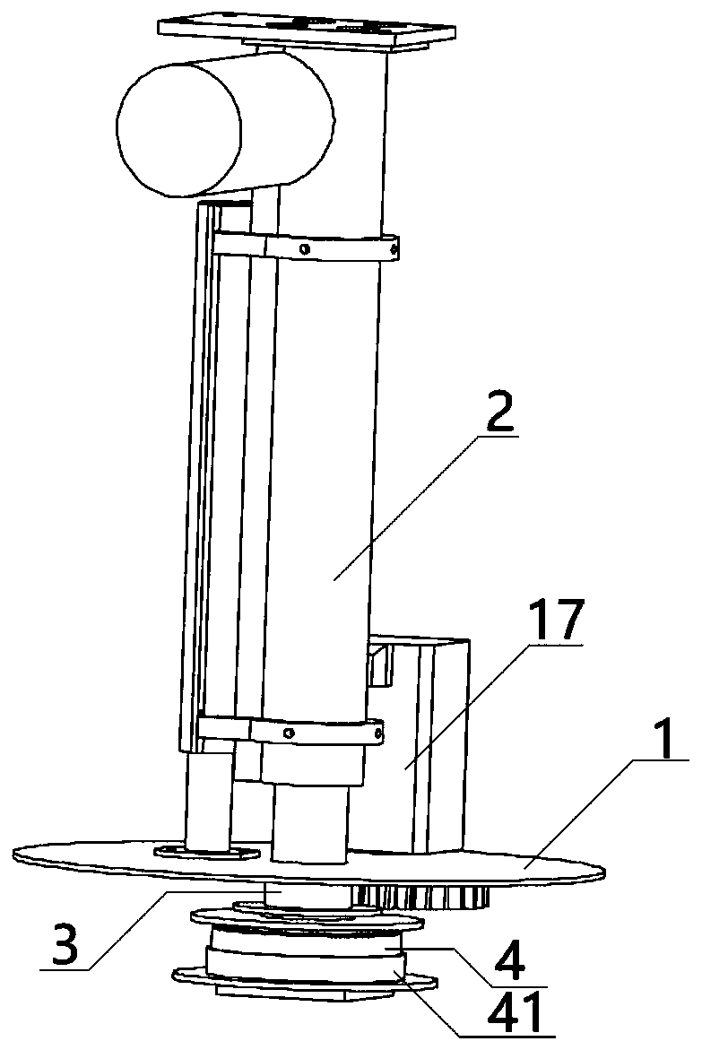
[0014] Such as figure 1 As shown, a kind of pushing and pressing vegetable cutter according to the present invention includes a mounting plate 1, and an electric push rod 2 is installed on the mounting plate 1, such as figure 2 As shown, the center of the bottom of the mounting plate 1 is provided with a hollow mounting sleeve 3, the bottom end of the push rod of the electric push rod 2 is inserted into the mounting sleeve 3 so that the electric push rod 2 is fixedly connected with the mounting plate 1, and the electric push rod 2 can drive Mounting plate 1 moves down and up. The bottom end of the installation sleeve 3 is provided with a bearing 4 and a bearing seat 41, and the bearing 4 and the bearing housing 41 connect the installation sleeve 3 with the vegetable serving tray 5, so that the vegetable serving tray 5 can follow the drive of the electric push rod 2. Mounting plate 1 moves down and moves up, also can rotate around vertical axis, and the rotation of this veget...


PUM


Abstract

The invention provides a pushing and pressing vegetable cutter, which comprises a dish containing plate rotating around the self vertical shaft. A plurality of dish containing areas are distributed onthe dish containing plate around the vertical shaft; a plurality of different types of cutters are movably and vertically arranged between the dish containing area and the vertical shaft; one pushingand pressing plate corresponds to a plurality of dish containing areas and a plurality of cutters, specifically, the dish containing plate rotates around the self vertical shaft, the dish containingareas reach pushing and pressing stations in a time-sharing mode, the cutters also move to be aligned with the pushing and pressing stations in a time-sharing mode, the pushing and pressing plate extends into the dish containing area already reaching the pushing and pressing station and then pushes and presses the food materials located on the pushing and pressing station towards the vertical shaft to penetrate through the cutter, a gap is reserved in the vertical shaft to allow the food materials to penetrate through the cutter to enter, and the end of the vertical shaft is opened to discharge the dish. The vegetable cutter provided in the invention is lower in cost, smaller in size and more convenient to use.

Description

technical field [0001] The invention relates to the field of automatic vegetable cutting, in particular to a pushing vegetable cutting machine. Background technique [0002] The ingredients need to be cut before cooking, and different cooking needs need to be performed on the ingredients, such as cutting the ingredients into different shapes such as segments, slices, strips, and grains. At present, common food cutting devices can be roughly divided into two types. One is to install the knife holder on the knife holder, place the food material on the knife, and push the food material to the knife to make the food material pass through the knife to achieve cutting. , when the food material cutting device needs to cut the food material into a specified shape, the specified knife needs to be installed on the knife holder in advance. If the food material needs to be cut into other shapes, the knife needs to be replaced, which leads to the use of Inconvenience, when food material...

Claims


Application Information

Patent Timeline
IPC IPC(8): B26D3/26B26D3/18B26D7/06B26D7/32B26D7/26B26D11/00A23N12/02
CPCB26D3/26B26D3/185B26D7/0608B26D7/32B26D7/2614B26D7/2628B26D11/00A23N12/02B26D2011/005B26D2210/02
Inventor 傅峰峰江志强丘健强朱达成蔡顺发
Owner GUANGZHOU FUGANG WANJIA INTELLIGENT TECH CO LTD
Features
  • R&D
  • Intellectual Property
  • Life Sciences
  • Materials
  • Tech Scout
  • Unparalleled Data Quality
  • Higher Quality Content
  • 60% Fewer Hallucinations
Learn More